The Marantz Integrated Amplifiers happen to be one of my favorite 70's Marantz pieces. Being a big fan of the 2230 similar 1060 Integrated, I knew id love the like sound of the 1030 Integrated. Rated at a conservative 15 Watts a channel, the 1030 uses a very similar pre-amplifier topography again as the 1060. The phono stage features shielding I haven't seen yet on any 1060's either.
Power Supply;
The regulated 35V+/37V+ power supply is fairly straight forward on this model, replacing electrolytics with high temp, long life Panasonic FR/FC's. Several Carbon Composite resistors were replaced as well with MOX Flame-Proof, all glue was removed.
The filter caps in these are positioned smack in front of the amplifier sections, which of course is a source of significant radiant heat. I like to come back, same with 22XX receivers who position these against driver sections, but I like to install a smaller foot print electrolytic here. This increases the overall area around the drive boards and decreases the subjected heat these caps experience. I increased the values here past the 20% extreme at 4700 for 2200 and 6800 at 4700's microfarads. To finish up a new 7A EG1018 power switch and X1Y2 rated safety capacitor was installed.
Pre-Amplifier
Again, with such a close topography minus the 1st stage, to the bigger 1060 Integrated I want with a similar compilation. Using low impedance PW's and Elna Silmics and small values with WIMA film capacitors. the coupling stage original Mylars were replaced with a Polypropylene MPK Solen.
Marantz 1030
Marantz 2230
Phono
The phono stage was similar to others, updating 2SC458 Bi-Polar Transistor pairs to KSC1845's and Elna Silmics/PW's. Its important to notate that C909/910 is an axial type electrolytic shunted with a 100ohm 1/4W resistor to ground.
Driver Stages
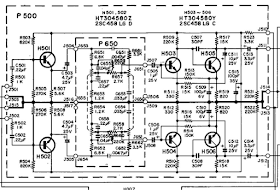
One important update to perform on the the symmetric driver stage is the H715/716 Diodes (1N60) to a series of 1N4148 diodes for reliability and adding Bourns Precision 500/100K trimmer potentiometers. Differential Pairs to matched Hfe 1845's. The coupling C725/26 and 01/02 were upgraded with polypropylene Solens and WIMA MK film capacitors, Elna/PW's were used for electrolytics throughout.
OUTPUTS
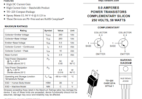
Several variations on output devices were tried and tested due to a repair required. original TO-66's are hard to come by, I recommend for a different option using MJE15032 NPN TO-220 type BJ-Transistors if necessary with some slight heatsink modifications and SilPads.


