AUDIO SERVICES

Saturday, February 25, 2017

Fisher 800C Receiver Restoration


Fisher 800C Receiver 


Today were featuring a very special tube receiver..the Fisher 800C considered by many to be one of the best receivers ever made available. The Fisher 800C was released after the early 500/800B in 1962 as an upgrade to the Fisher 500C which did not include AM reception and MPX integration.  The Fisher 400/500/800C utilize a compliment of 7591 power tubes for a 30-35W .7% THD rated output factory output with a fixed bias.


As often with these old tube amplifiers, and receivers their are a few major contenders that need to be addressed such as the coupling network for the output stage, modify the 7591 fixed bias topologies amongst others outlined below.


7591 Output Stage
Several modification were integrated into the output stage which allows for bias matching between 7591, regulating the negative bias voltage and changing the coupling networks and grid resistors.


The original designed uses a .047/400V coupling capacitors with a 330K grid resistor. For more reliability and to handles todays tubes better we replaced the grid resistors with 200K ohm resistors to limit the value of reverse grid current  voltage under maximum rated dissipation. In connection we replaced the 7591 coupling capacitors with four .1/630V high grade MKP polypropylene film capacitors with a noted increase in operating voltages in order to help maintain time constance in the RC coupling circuit at the driver/output stage with the decrease in grid resistor resistance. 


After the coupling stage is complete we move onto the 7591 screen stability modifications which is straight forward; I isolated each 7591 from the original buss lead and daisy chained the Pin 1 input with a inline 100OHM resistors to pin 4 after relocation the Pin#8 feed, this effectively eliminates transient arching that can severely damage tubes.


Finally for the output stage we integrate what called a IBAM designed by Drew Bolce for early Fisher versions. The IBAM (Independent Bias Adjustment Modification) removes the fixed bias circuit and allows the individual bias adjustment of each 7591 output respectively to 32mA draw. The IBAM was built using low impedance high temp (105C) Nichicons after trying out FC Panasonics first and carbon film resistors then  installed on the chassis through a new mounting point near the output tubes…along with the Bias 10OHM cathode resistor modification allows for easier and accurate bias settings.  Last checked I was able to adjust to a perfect -22.05Vdc @ 30mA-30.5mA for all four 7591 :) ... nice


Output Testing Notizen

PS Modifications
With the above IBAM modification we installed a way to attenuate the negative dc voltage rails for the bias circuit and pre-tubes using a 10K precision Bourns potentiometer along with replacing the original Siemens selenium bridge rectifier with a modern BR3 type 8A 400V+ bridge rectifier. As the negative voltage is increased this reduces our current draw allow to dial in the appropriate voltage for biasing modern tubes. Often times the required -22V is lacking in unrestored models causing bias issues. 


The original cardboard dual capacitors was replaced with 1000MFD low impedance high temp (105C) Nichicon PW capacitors as well as the associated .1MFD film to a high grade Mundorf Tube M Cap 630V. The B+ developing diodes CR6/7 were replaced with modern 3A Fairchild diodes. The .01 large axial capacitors were replaced again with high grade Mundorf EVO Oil type .01/630V film capacitors for better protection and filtering. 


The remaining capacitors for the 12AX7 drivers were replaced with high grade MKP polypropylene film capacitors with an increase to 630V operating voltages. The original axial electrolytic were replaced with low impedance high temp (105C) Nichicon PW capacitors with an increase in operative voltages as well as associated carbon film resistor changes. Also replaced with the C111 8MFD  to a high grade MKP polypropylene 630V film capacitor. 


The front end AM/FM capacitors were all replaced with high grade WIMA polypropylene 630V rated and MKP polypropylene 630V film capacitors including the MPX 1MFD and all associated .022MFD/.047 couplings. 


New LED’s installed in both front glass slides and Meter indicators.


Audio Notizen


Monday, February 20, 2017

Bill's Adcom GFA-555 Power Amplifiers Driver Rebuild

Two Adcom GFA-555 Power Amplifiers 


Today were showing a pair of Adcom GFA-555 Power Amplifiers that came in for driver board updating and testing.  The Adcom GFA-555 is still today one of the most popular, affordable power amplifiers on the new and used markets. Designed by the famous Nelson Pass with Adcom in the mid 1980’s which was later proceeded by the Adcom GFA-555 MkII Amplifier. The major differences in the MkI and MkII is the integrated of a DC servo circuit and a bit more beefier output/driver stage modifications of which Nelson Pass did not have a hand in.


The GFA-555 uses a pair of sturdy plastic 5-way binding posts with gold plated RCA inputs and a bridged/Stereo switch. Ive noted several complaints, as one of these unit exhibit of failing rocker switches for some reason.   The GFA uses a large Toroidal transformer and dual rectification stages with each 30,000 microfarad filter per side. 

I have always found the GFA-555 to be an incredibly well built and operating amplifier, very passive power design with no major characterization to add to the mix..exactly what we want in a power amplifier.  The only downside, which is quite major due to the fail types seen in these, is the lack of any protection. In-Line speaker fuses are highly recommended running these amplifiers. 


Driver Assembly
The  GFA uses a pair of NPN initial differential devices which were replaced with low noise Fairchild TO-92 transistors matched within 1% and thermally coupled for more stability, along with a constant current configuration for stabile Bias operation with a solid constant voltage bias eliminating thermal run-off and other drift issues. Pre-Driver BJT devices were replaced with modern low noise TO-126 Fairchild devices as well.
*thermally coupled 1% matched differentials 

The Adcom GFA-555 is well known to have faulty electrolytic used during construction. All of the electrolytics were replaced with new low impedance high temp (105C) Nichicon PW capacitor with an increase in operating voltages. The original metal 1MFD film I found to be of poor construction, this was replaced with a high grade MKP Polypropylene film capacitors along with the .1MFD mylar to high grade  .1MFD MKP Polypropylene films


BEFORE


AFTER


**Constant Current Notes GFA-555

The GFA-555 has such a stabile bias because the main output devices (Q13-Q20 NPN/PNP) in connection with 3rd stage Q11/12 emitters to help create a simulated circuit through R19/20 to Q9/10 which establishes a constant current at R21. This is achieve through matching the devices with Q11/12 creating an established Iref (Current Reference.)


Audio Notizen (Ser# 182/374)


Saturday, February 18, 2017

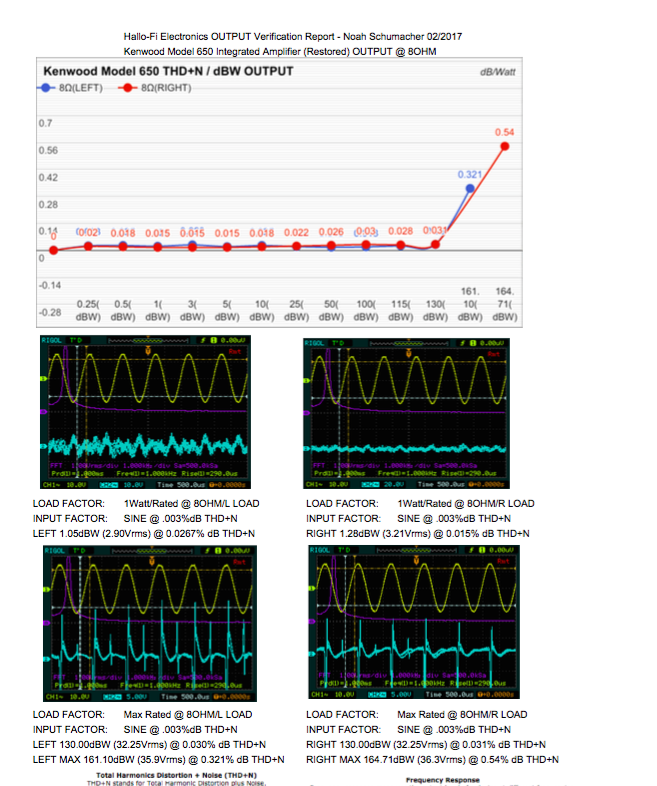
Mike's Kenwood Model 650 Restoration

Kenwood Model 650 ( Model 600 ) Integrated Amplifier


Today were showcasing a rare Kenwood Model 650 Integrated Amplifier. The Model 600/650 were made during 1973 to 1979 from Kenwoods limited special order only Supreme series. More often sold over-seas or select European/Asian markets these are incredibly rare Kenwood machines!  The Supreme series comprises the Model 500/600 and 650 Integrated Amplifiers, a 600T/650 and 700T Tuners and a 700C/700M Power Amplifier. With less than 1000 produced of any given series the KA-907 is the latter 600 adaption.


Power Supply & Rectification/Protection X00-1700-10 / X00-1700-10
The 650 power supply is unique in its monolithic topology using two transformers and a regulated dual mono configure PCB. The stabilized X00-1720-10 assembly produced a dual -/+ 28 V and 40V rails. This PCB unlike any other is secured via a vertical slide mount thats secured to the chassis.

BEFORE


AFTER


This PCB has a large amount of glue used to mount the large 220MFD capacitors that eat away at the Dz9 diode and associated resistors. These resistors were replaced with KOA carbon film 1/2W and a new modern 4148 diode. All the glue was watched off and cleaned. 
All of the TO-220 regulating BJT’s were upgraded to heavy duty On-Semi MJE TO-220 devices along with the 415 to a modern TO-126 Fairchild device and TO-92 low noise devices. All electrolytic were replaced with high temp (105C) long life Panasonic FC and Nichicon PW capacitors with an increase in operating voltages.  along with two VP Nichicon BiPolar capacitors.


The protection assembly is located next to the PS PCB and shared with the PS topology featuring a DC deviation detection and fused overcorrect protection. A MY4 Omron was installed onboard and new Vishay X1Y2 Safety capacitors.

Amplifiers PCBs X07-1440-00
The Model 600 650 utilizes an extremely unique and reliable front end. Comprised of a JFET 2Sk58 IC and a NPN BJT’s designed as a “Butler Front End’”  which is a very low noise, high linear front end using JFET’s and BJT’s. 


BEFORE

AFTER


This front end is encompassed in a shielded and thermally isolated area!  The front end differential BJT’s were replaced with modern extremely reliable ZTX TO-92 devices. The Bias, ASO and constant current BJT’s were all replaced with modern TO-92 and TO-126 Fairchild devices. New precisions Bourns potentiometers installed and all film were upgrade to high grade, audio type WIMA polypropylene film capacitors. Electrolytic’s were replaced with a Nichicon FG Fine Gold and low impedance PW with an increase in operating voltages.


 **I did however go back to the original 2SB/SD driver pair compliment for reliability and discrepancies I noted during output tests.


AF Stages X11-1310-00 & X08-1560-10 & Filter X12-1130-10


The Model 600/650 boast an exceptional 44-stepped ALPS Potentiometer featuring 
plastic resistive volume and co-axial balance control.


The entire AF stage is built of JFET compliments seen in many of the high-end topologies of the time. The RIAA EQ is a differential JFET stage with a Class A/Buffer JFET and output stage for an extremely linear and quite stage. All of the elelectrolytics were replaced with a low impedance Nichicon PW and audio grade FG Fine-Gold and KT capacitors with an increase in operating voltages. . New WIMA polypropylene films were upgraded as well.


BEFORE


AFTER


The Tone control  (X11-1310) is a flat amp (19.5dB Gain) and BAX type control using shunt regulated push-pull differential and constant current circuit, using a Class A FET output. As above Nichicon FG/KT audio capacitors were installed with an increase in operating voltages. 


The Filter stage is a NFB filter with a constant current circuit with a LoPass @ -12dB/Oct 40Hz and -12dB/Oct above 8Khz.  Capacitors upgrades here with WIMA polypropylene film upgrades and Nichicon Fine Gold FG audio grade capacitors with an increase in operative voltages. 


Photo showing just how fun the Kenwood Model 650 can be.... (sic)


Filter Capacitors
The dual mono supply utilizes two per side 18,000MFD capacitors which were replaced with modern quality Nippon/Chem-Con 18,000MFD 75V capacitors for a 72,000microfarad potential storage total


AUDIO NOTIZEN