Monday, January 11, 2016

Pioneer SA-8800 Integrated Amplifier

Pioneer SA-8800 Integrated Amplifier 


The Pioneer SA-8800 is an integrated amplifier sold from the late 79 to early 1982. with a fluorometer assembly the SA-8800 touts Pioneers proprietary Non-Switching Amplifier topography further discussed below.  The A/B Class A constant configuration lends to impressive output without the associated distortion of typically b operations. 

Power Supply AWR-182
The power supply is a switching design with relay protected output. All the electrolytics here were replaced with high temp (105C) Panasonic FC capacitors and low impedance high temp (105C) Nichicon PW’s. along with the relay snubber to a 10 OHM/.1 polypropylene. It was noted that one 390 OHM wire wound was damaged and replaced with a 5W WW type. Relay contacts were cleaned and re-installed after a clean-bill. The 10 Ohm 1W resistors had drifted and were updated to 1W MOX type. regulating drivers 2SB682/D712 were updated to modern TO-220 MJE devices. 


Filtering
This unit had oxidization one some of the filter capacitor brackets so new 40MM brackets and all new high grade  12,000 MFD 80V Panasonic THA low ripple filter capacitors installed. The 8800 uses X4 of these 12KMFD capacitors! I was happy with how the aesthetics of this turned out.


EQ/RIAA GWF-113
The SA-8800 is known to have a superb RIAA stage, I believe due to the low noise BJT field and super complimentary, symmetric SEPP topography. The RIAA/EQ stage had all the electrolytics replaced with audio Nichicon MUSE and audio grade Nichicon MUSE Bi-polar compliments with low value capacitors to low impedance high reliability Nichicon PW’s. 


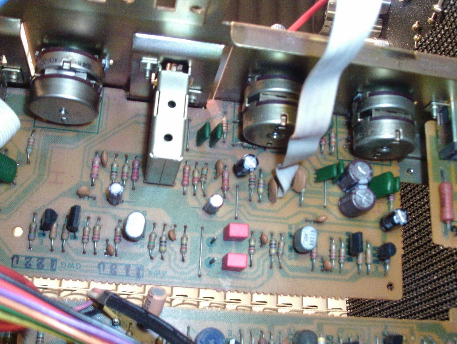
Tone  GWG-122 twin FET
The Tone control/pre stage uses like the driver below a complimentary low noise pair of differential Dual FET packages (2SK129A) and a final stage dual BJT (PNP) 2SA798 device.  Like many tone controls we do the electrolytic were replaced with audio grade Elna Silmic and low value microfarad to 1UF high quality polypropylene WIMA film capacitors. Low impedance Nichicon Bi-Polars (4.7MFD) installed as well. With the Meter and RIAA PCB’s removed from the chassis panel you can easily access all the controls and potentiometers at this angle. 


Meter PCB AWV-001
All the electrolytics were replaced with low impedance , high reliability Nichicon PW’s. The potentiometers for meter dialing cleaned pins to amplitude IC HA12010 (Q3/4) were reflowed and Q2 D712 transistor updated to a TO-220 MJE device.
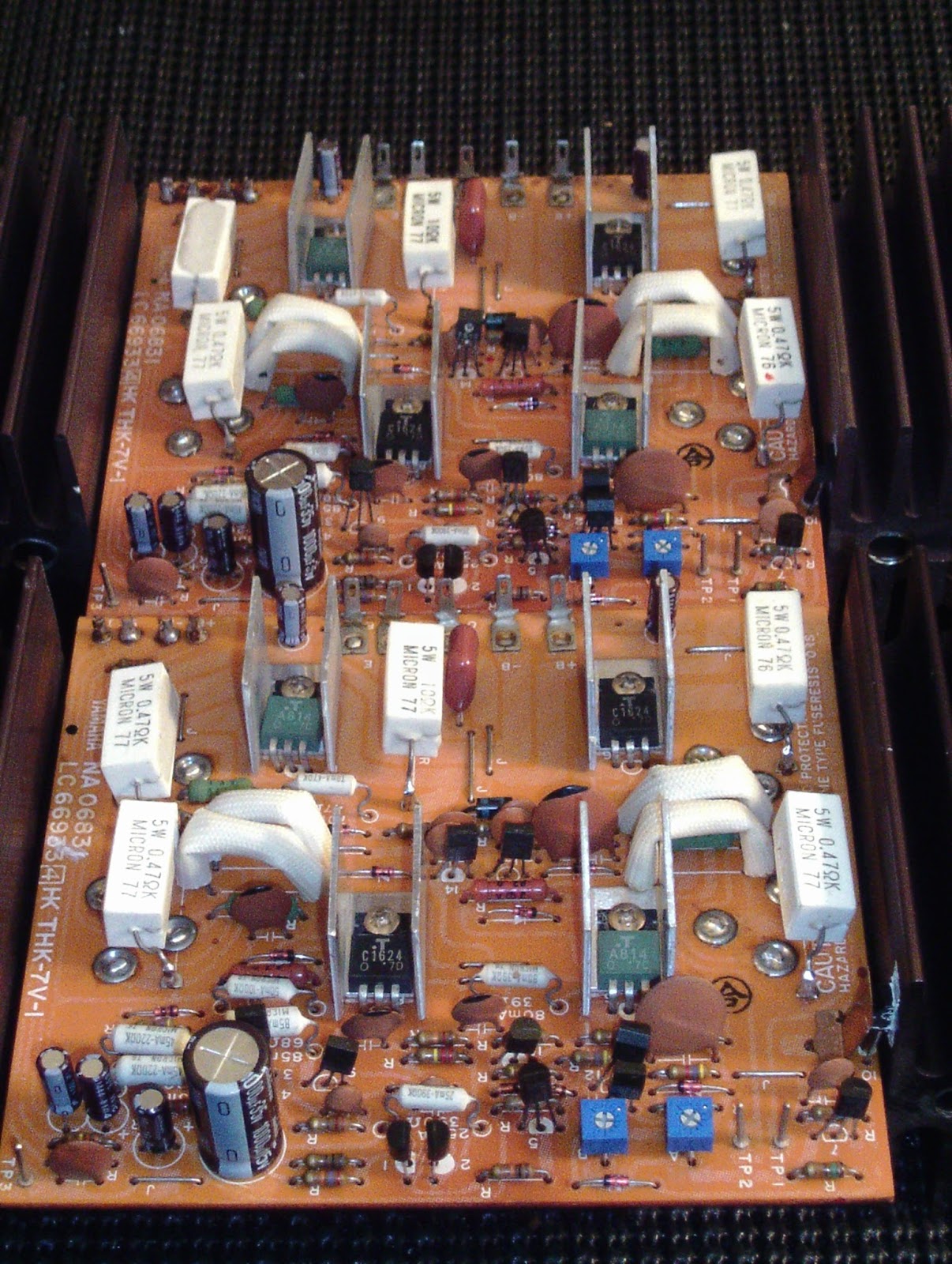


Driver GWH-115
Like the SEPP RIAA stage and two tier pre-amp driver stage the PA uses again a dual differential FET 2SK129A low noise device which are a reliable device still and damn near unobtainable. 1st stage differentials are driven by a dual PNP BJT package with  complimentary differential NPN dual package in a constant current stability mirror arrangement for stabile gain drive. A 2nd their darlington arrangement and final PARA-SEPP circuit for the „Class A-B“ NSA circuit dependent on a SL-RET (IC array) with cleans up our high frequency distortion response as well usually associated with high running class a type configurations.  I am currently reviewing a dual package replacement with slow progress for future repairs. Note also the orientation of the large TO packaged output devices under the PCB and large "skived T-Curve" heatsink. Its lighter than the typical heatsink with a reported 50% increase in dissipation but I still hate these, their flimsy, I personally prefer a large metal and TO-3 device for reliability sakes. I think mounted under the chassis as so leave the legs susceptible to high heat from the radiance above potentially weakening the solder joints on the outputs, I reflowed these in this case. 


All driver electrolytic capacitors were replaced with high temp (105C) low impedance Nichicon PW and high temp Nichicon Bi-Polar capacitors (4.7MFD). All bias mid and offset potentiometers were replaced with precision Bourns trimmers. Final Stage  2sc1913/913 drivers were update to modern complimentary 2073/94o KSC/KSA TO-220 devices.


This SA-8800 had developed a under duress load issue, a final output BJT device was failing under full consumption; thus shunting the rails directly to the output as common with end stage BJT failure resulting in a constant -48V offset. Beyond the voltage indicators this type of failure will not be detected in a standard BJT test under typical 5+/-V DUT's.

cross-referenced new Sanken output devies in a TO-3LP package


Final output results as follows (dual CH)

(120Vac) 10Khz @ 8.00 load
links                          recht

4.73 (2.76W                  5.64   (3.97W 
9.28 (10.76W                10.72 ( 14.36W
15.69 (30.77W              17.96 (40.32W
20.35 (51.76W                  23.70 (70.21W
26.90 (104.40W                  31.46 (123.71W


clipping achieved 
26.90 (104.40W                  31.46 (123.71W


Friday, January 1, 2016

Yamaha CA-1010 & CA-2010 Amplifier Restorations

Yamaha CA-1010 & CA-2010

CA-1010 Yamaha 


CA-2010 Yamaha


Here we have two Yamaha CA Integrated Series amplifiers.  The CA1010 and CA2010 are both similar models with a few distinct differences. 

For starters the CA2010 utilizes all enclosed and some stepped ALPS potentiometers. The other is the control IC for the metered circuits. Another differences is an increase to 22,000 microfarad filter capacitors vs 18KMFD in the 1010 amongst other class A and A/B integrations for stability including all matched FET's. 


Power Supply & Protection PCB’s
For both the CA1010 und 2010 they are almost identical designs for the Power Supply,protections circuit other than the slight difference in lamp rails.  For all the electrolytic’s we replaced with high temp (105C) Nichicon PW and Panasonic FC capacitors. Diodes updated to UF type general diodes. New Omron LY relays were installed as well as at the filter cap PCB.  The power supply on each also use a pair of 10 and 2.2MFD bi-polars which were replaced with Nichicon EP which come in available 105C temperature variances.  I want to note its important to remove the component glue thats used on the 1000MFD/330/220MFD capacitors.
CA1010


CA2010


Pre-Amplifier/ Tone Control
Again very similar topographies used in both the 1010 and 2010 models. As noted one of the biggest differences is the use of enclosed stepped potentiometers for the tone and enclosed pots for the Volume and Balance controls. The few electrolytic’s populated here were replaced with audio grade Nichicon KA capacitors. Both PCB’s incorporate a lot of low Mylar film values, In my experience with the CR series swapping these out with polypropylenes didn’t lend the best results. We did try the .56KMFD with a PP type but resorted back to the Mylar films in this case.

CA1010


CA2010


Function/RIAA, Coupler & Meter PCB Assemblies 
The difference in the tone/RIAA centre is the replacement of IC103/4 with yamaha IC #; MC#00164, in a matched FET, DIP package than the 2010 models. Some models also contain a difference at D101/102 diodes and should replaced the VD1212 glass pack with a 4148 in series respectively.  The CA2010 also introduces the front end 3.3MFD and 1MFD electrolytic’s. The lower value 1MFD were replaced with PP type WIMA film capacitors and all others with low impedance Nichicon PW or audio grade Nichicon KA front and back.  The series of 220/33MFD tantalum capacitors were all replaced and upgraded to audio grade Nichicon KA/PW low impedance electrolytic capacitors in both CA1010 and 2010.
CA1010


CA2010


Meter PCB’s NA06836 and CA1010 both had all the electrolytics replaced with low impedance high temp (105C) Nichicon PW capacitors. The 2010 uses a integrated PM-02 IC where as the 1010 uses a series of BJT circuits for control. The ca2010 lacks the shielding the BJTs need on the 1010 models. 

CA2010


Also dont forget the coupler PCB on the rear chassis, two axial should be replaced with with modern Nichicon TVX, as I noted in other rebuilds the quality of axial's from this time period is questionable.


Drivers
The neat thing about the CA 1010/2010 is the Class A/ B operation feature. Unlike later models that incorporate micro-switching i would advise to never “Hot-Switch” the features, the Class A operation has a significant higher operating parameter as well at about 138-148 Fahrenheit Vs around 100F in A/B. (complied averages: multiple users)

CA1010
All the electrolytics on the 1010 were replaced with high temp (105C) low impedance Nichicon PW’s, the original film was replaced with a high quality polypropylene Panasonic ECW film capacitors. Its important to update again the glass pack VD1212 at D301 with 4148 in series. First stage differentials were replaced with matched 992 BJT’s and 2nd tier TR303/304 with matched 2383YBU BJT’s.  The original 2.2K ClassA/B potentiometers were replaced with 2.2K 1/2W Bourns precision trimmers. Because of the dual operations their are two bias points.

Audio Notizen CA1010
punkten beim TP1 und TP2 fur A/B 25mV 
punkten beim TP1 und TP2 for A 280mV


CA2010
Again, electrolytic here were replaced with high temp, low impedance Nichicon PW’s and films replaced with polypropylene Panasonic ECW’s films. their are no VD glass pack diodes to address on this assembly. The CA2010 differs by using a dual FET differential IC rather than matched BJT compliments.  We did however upgrade the 3rd stage driver compliments to modern On Semi MJE15030/31 TO-220 transistors replacing the 2sc16234/2sa814 compliments.  The 2010 also utilizes a mid-bias point potentiometer which directly correlates to mid stage drive so setting this will greatly affect your bias and output points. All the original 2.2K potentiometers were again replaced with precision Bourns potentiometers.


Audio Notizen CA2010
punkten beim TP1 und TP2 fur A/B 25mV
punkten beim TP1 und TP3 fur 0V
punkten beim TP1 und TP2 fur A 300mV


A different approach I took after comparing fusistors. In the 1010 we have hear all are well with 2% tolerance still, yet on the 2010 most seemed to be drifting about 5% high. Its very important to do your math when converting fusistors to metal films or the like as we did here. The fusistors in this stage short excessive consumption after a failed BJT device, thus shunting and protection the distal operating circuit from the failure point. We want the same characteristics now but in a more reliable resistors such as films. so we take IxR =V V/R .

IE:  
FR301/302 (4.7/230mA) 4.7ohm 1/4W  (4.47 und 4.35) (.2486 W dissipation) 
FR303 (100/50mA)  100ohm 1/4W (100.91)  (.25 W dissipation) 
FR304 (68/85mA)    68ohm   1/2W (68)      (.4913)
FR305 (390/25mA)  390ohm 1/4W (393) (.2873 W dissipation) 
FR306 (47/70mA)  47ohm 1/4W  (47) (.2303 W dissipation) 


Both CA1010 and 2010 filter capacitors were replaced with low ripple Cornell 22,000 microfarad 100V capacitors and fitted. The final step included converting both circuits to Dc rectified LED illumination.  The 14V rails for the lamp assembly needed to be adjusted at the voltage divider so a 180 Ohm 3W resistor was installed with a 1A/100PIV diode in line and 1000MFD filter capacitor for smoothing giving us a correct operating voltage for X5 3.65Fvd White LEDs at 100mA draw. (thanks Joe on the Math)

CA1010


CA2010


3.5V 20ma LED adapted festoons 

LED Conversion notizen fur CA2010

14.8Vac W/ 1A/100PIV diode w/ 1000MFD capacitor @ 19.8Vdc
para: 3.5Fvd 20mA

19.8Vdc - 16.3Vdc working
16.3Vdc / (.020x5) = 163 Ohm V/I=R
16.3Vdc x 0.1 = 1.63W (3W min)


PCB mid-modification procedure; notate inrush R and filter (C)


Saturday, December 26, 2015

Sansui 1000A Tube Receiver

Sansui 1000A Tube Receiver 


We had two Sansui 1000As come in recently, one with a bias rebuild we did a few months ago back for a full restore as well as the other. The 1000 came in a transistor and valve topography, with the 1000A being a very collectible receiver. Rated at a fairly modest 40W/Ch using a compliment on each channel of two 7591 power valves. The clincher Sansui utilized with the 1000A is the use of MASSIVE high quality Hashimoto Electric output transformers, Hashimoto started in 1958 and lead its production facility to almost exclusively Sansui at the time. Today Hashimoto has delved into their own series of HiFi valve amplifiers. I cleaned and work the tracking on the existing potentiometers, if you have any trouble tracking replace with a 10K multi-turn instead. 


Output Stage (7591)
An interesting thing to note on the 1000A series are the variants of the bias circuits implemented. Several biasing configuration are out there using a series of one, two or four bias potentiometers to bias a pair of individual sockets.  Both of these comprise of the independent pot design, which is better as we can dial in each specific tube. As I highlight in our past 1000A posts its important to add a 1/4W 10 ohm resistor from the cathode (pin 5)  to ground of each 7591 valve, this gives you an added protection of destroying the resistor first shunting the tube and a stabile bias parameter. using our bias formula and the 7591 dissipation factor were looking at about 32mA each cathode or 325mV across the resistor (325/10) 32.5mA

Dual Potentiometers

Quad Potentiometers 


Present in the 1000A are tons of oil-type electrolytic capacitors which are well known to be failure prone if not actively failing at this point in their life due to the inferior construction of axial oil-type of the period. All the 1microfarad and larger values were replaced with quality Nichicon TVX axial capacitors up to the 250V+ rating components. Electrolytic in the bias stage were replaced with 630V polypropylene Solens and accompanied resistors replaced. 1microfarad and smaller oil-type were replaced with high quality Panasonic ECW polypropylene film capacitors from .00047 to .1MFD. 


form fitting new axials


Nichicon were used for the filter cap replacements on top and stuffed cans with 40mm diameter. The 40mm 220/220V capacitors had their respective SW-05 diodes updated to 1.5/700V UF4007 diodes in parallel with a .0051 film capacitor along with the isolated SW-05. 

 SW-05 Updated


New 8-pin octal sockets were install for all four 7591 power tubes. The rear RCA’s connectors with buffed along with the OPTs removed and chassis buffed at specific points as shown, the end result was phenomenal, almost mirror like!


Before

After


Buffed RCA Inputs


 I was incredibly impressed with the end result, with the bias dialed in on matched 7591’s and the oil-type removed the 1000A will continue to be as reliable as can be with plenty of power, very smooth yet deep sounding. 

Our Test Station @ Hallo-Fi

Audio Notizen (results) 

Pin cathode bias beim 10Ohm final*
ein 322
zwei 325
drei 325
vier 325

10Khz beim 8Ohm
Recht
3.13V 1.12W (30dB)
4.98V 3.10W (34dB)
10.17V 12.92W (41dB)
16.57 34.32W (45dB)

Links
3.36 1.41W (31dB)
5.20 6.36W (38dB)
9.0 10.12W (40dB)
16.26 33.04W  (45dB)


5.20 (6.36W) (38dB)


9.0 (10.12W) (40dB)


16.26 (33.04W)  (45dB)