Pioneer SX-850 Receiver
Here we have a nice Pioneer SX-850 receiver. Produced from 1976 to 1977 it was a mid entry SX series receiver. Prized for its direct coupled phono section the SX850 also presents an honest .1<% THD noise floor at a very modest 65+ W/CH. Like many of the SX series, the 850 offers a superb RF section featuring a 4 gang tuning capacitor and FM/AM MOSFET drive/lock.
Power Supply AWR-101
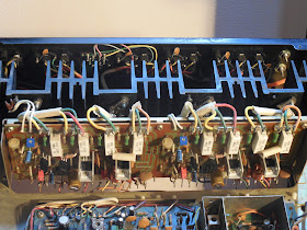
On the power supply PCB were several noted back electrolytic capacitors, many of these smaller SX series exhibit significant radiant heat issues on the 850, mostly due to the fact that its oriented under the chassis, sandwiched by the bottom plate and through natural convection offset of the heatsink mounted BJT devices and current limiting resistors. The electrolytic were replaced with high temp (105C) long life Panasonic FR/FC and Nichicon low impedance high temp (105C) capacitors. Q7 updated (2690AYS) and several general diodes to UF type. I also recommend reflowing all solder connection on this PCB.
New high quality Chem-Con 18,000/80V capacitors were used to replace the original 15,000/50V filter capacitors. and a .1MFD high grade ECW polypropylene film used for bypassing removing the original bypass resistor.
Protection AWM-062
Similar to the SX-828 we recently showcased, the 850 has a typical dc deviation detect circuit with a 24V relay. Such as the relay with the T-Cover the relay was removed and case flushed, a new MY2 was installed. Electrolytics were replaced with all high temp (105C) capacitors as Panasonic FR/ Nichicon KL hight temps (.22MFD/50V) and PW electrolytic along with the problematic 2SC1384 BJT updated to a 2690AYS device.
RIAA AWF-011
Again arranged very similar to the SX828, the 850 seated the RIAA assembly under the chassis near the protection assembly. A very clean symmetric design producing a very quite and nice phono stage. The electrolytic were replaced with a low impedance Nichicon PW and audio grade Elna Silmic II capacitors with Q1/2 725 class BJT’s updated to matched 992 devices.
Power Amplifier PCB AWH-059.
Extensive work was done on the driver section. Updated all the capacitors, using Nichicon PW high temp (105C) long life and audio grade Nichicon KA /Fine Gold capacitors. for the input 1MFD a high grade WIMA polypropylene film was installed. New precision bourns bias potentiometer and DC cleaned and lubricated.
The 1st order differential transistors were replaced with 1% Hfe matched ksa992 transistors, while the bias/2nd order 2SA818/1628 devices were updated to KSA1381/3503 BJ-transistors. 3rd order driver pairs were replaced with matched 5% MJE15033/32 transistors for a more heavy duty device and new thermal compound applied. The TO-3 output devices were pulled and new MICA insulators and thermal compound applied.
Audio Notizen
punkten beim #12 und 13 fur 20mV (VR3) & punkten beim #27 und 28 fur 20mV (VR4
DC beim G und punkten 9/10 auch 24/25 fur 0Vdc VR1/2
AF Flat -Amp AWG-038/AWG-039
Removing these sectionals isn’t too bad, this is where totally access to cleaning the switches/ rotary controls is for a proper cleaning. All the tantalum capacitors were replaced with 1<MFD replaced with audio grade Nichicon KA capacitors and the latter with high grade WIMA PP film capacitors. All others were replaced with audio grade Nichicon KA or low impedance Nichicon PW’s. The switching assembly (AWS-094) 220MFD was replaced with a Nichicon PW type.
RF PCB AWE-071
The remaining RF section was recapped with high temp (105C) low impedance Nichicon PW and Nichicon KL fur .47<MFD capacitors replacing the original tantalum capacitors.
LED Conversions
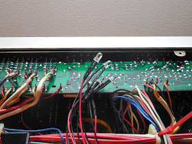
New globe LED’s and function indicators installed and routed. The new LED’s present a very brilliant clean white light, opposed to the original Amber. Much cleaner IMHO plus with the added benefit of less radiant heat and overall current draw.
Audio Notizen (8OHM @ 1.006Khz(.003THD) SINE)
1W/CH @ 8OHM <=.05%dB THD
LINKS (RATED 1W/CH @ 8 OHM <=.05%DB THD)
—2.85VRMS (1.015W) @ 0.018%DB THD+N
RECHT (RATED 1W/CH @ 8 OHM <=.05%DB THD)
—2.83VRMS (1.00W) @ 0.018%DB THD+N
33W/Ch @ 8OHM <= .05%dB THD
LINKS (RATED 33W/Ch @ 8OHM <= .05%dB THD)
—16.15Vrms (32.602W) @ 0.044%dB THD+N
RECHT (RATED 33W/Ch @ 8OHM <= .05%dB THD)
—16.25Vrms (33.007W) @ 0.044%dB THD+N
65W/ch Continous PV @ 8OHM <=.1%dB THD
LINKS (65W/ch Continous PV @ 8OHM <=.1%dB THD)
—24.81VRMS (76.942W) @ .051%dB THD+N
RECHT (65W/ch Continous PV @ 8OHM <=.1%dB THD)
—24.50VRMS (75.031W) @ .051%dB THD+N


No comments:
Post a Comment