
Marantz Model 19 {Fifty-Fifty} Custom~Calibrated Stereophonic Receiver


The Marantz Model 19 receiver is a legendary receiver sought by any Marantz collector and fanatic! Touted as a TOTL 50Watt receiver during the early 1970’s thru 1974 the Model 19 featured the early gyro tuning and coupled oscilloscope output display in the front with he series signature plastic capped black push-buttons. The Model 19 uses an appropriate amount of shielding for its build quality and employs a massive amounts of film capacitors in the cap coupled stages providing that warm lush Marantz tone.


A1 Power Supply & Time Delay
The Model 19 employs a regulated supply thats split for both high voltage 500/200V scope display and a full wave bridge rectified -/+36Vdc, -/+12Vdc & -36Vdc full wave rectified single and dual ended sources. The original design uses an array of 80 ohm wire-wound cement resistors which exhibit a fair amount of dissipation wear on the cement substrate. Careful and thoughtful placement of the new radials allows a perfect with the original cover and no pintout modification!
All of the original multi-cap capacitors were replaced with a better suited single radial, low impedance, high temp (105C) Nichicon PW type electrolytic capacitors with an increase in operating voltage and capacitance in serval DC input coupled stages for better filtering. The 3-5Watt zener’s were all replaced including the original full wave and bridge rectifier diodes with a ultra-fast, soft recovery type Vishay diodes. The original cement-wire wound resistors were all replaced with Vishay precision, silicone coated resistors.


BEFORE

AFTER


REGULATED VDC CONFIRMATION


A14 Time Delay
The populated axial capacitors, which I am not a fan of due to a typically reduced quality in construction were all replaced with a low impedance, high temp (105C) Nichicon PW type electrolytic capacitors with an increase in operating voltage.
BEFORE

AFTER

Filter Capacitors
The large chassis mounted, full wave bridge rectified filter capacitors were replaced with computer-grade CDE 10KMFD filter capacitors with a reduced profile due to the proximity to the perpendicular mounted driver board.


-/+B CONFIRMATION


A8 RIAA EQ (PHONO)
The phono assembly uses a simple PNP gain stage with NFB and can coupled input/output in a very similar fashion to the P400/700 design with clipping adjustment. A -36Vdc source drives the phono stage. This PCB also mounts the separate volume and balance potentiometers.
All of the small signal devices were replaced with a high gain ZTX DI Eline type devices. Clipping adjustments were replaced with precision, sealed Bourns potentiometers. The input/output compliment was updated with high grade precision CDE, MKP WIMA polypropylene film capacitors.

BEFORE

AFTER


RIAA CURVE RESPONSE MODEL NO.19

A10 Tone Front End & A11 Filter
The front end tone stage uses a large amount of yellow film capacitors, which tend to have a noted failure rate, these are used quite a bit thru out the Model 19. The audio stage is a more complex NPN/PNP gain stage/NFB design with a +12/-36V input and cap coupled input/output.
All of the small signal devices were replaced with a high gain ZTX DI Eline type devices. All of the electrolytic capacitors were replaced with low impedance Nichicon PW type with an increase in operating voltage. All of the films were upgraded to a high quality WIMA MKP type polypropylene film capacitor. The chassis mounted C3 can cap was replaced with single radial low impedance Nichicon PW type with an increase in operating voltage and capacitance for better filtering. Input films on the filter assembly were updated with a high grade ECW polypropylene film capacitors.

BEFORE

AFTER


A12A/B Drivers A13A/B PA
The amplifiers are divided into a driver stage front end and a separate power/current gain stage output with a complimentary output pair. The feedback is routed via a integrated relay protection that can tend be problematic due to the poor relay construction and NFB design. One may consider bypassing the integrated relay.
The input differential pairs which can often cause DV offset stability issues were replaced with matched high gain ZTX DI Eline type devices and original mounts removed for direct solder placement, these significant reduce DC drift in the design. The clipping and bias adjustments were all replaced with precision, sealed Bourns potentiometers. The original wire-wounds on the PA and driver stage were all replaced with new Wire-wounds and MOX type resistors.

All of the electrolytic capacitors were replaced with a low impedance type Nichicon PW and the original axial replaced with a better quality radial MUSE BP Nichicon capacitor. All of the films were upgraded to a high quality MKP WIMA polypropylene films.

BEFORE

AFTER


DIFFERENTIAL MAPPING

BIAS CONFIRMATION


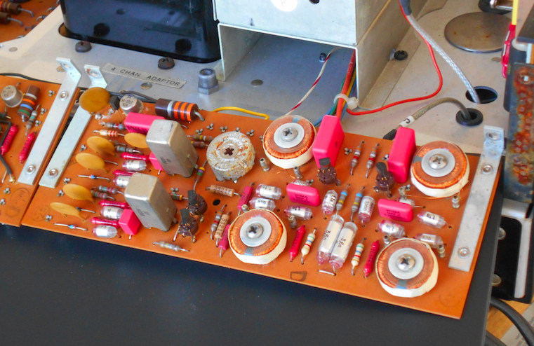
MPX Matrix & MPX Oscillator / RF &Scope
The MPX stages are uniquely mounted perpendicular to the chassis very simple brackets mounts on the rear of the unit top side with isolating material covering the foil side from the chassis cage. The RF Pcbs are shielded properly, especially around the scope display.
All of the films were updated on both assembly with high grade MKP WIMA polypropylene film capacitors, the 1MFD coupled axial on the scope assembly were both replaced with a robust high quality ECW polypropylene films. The original axial was also replaced with a TVX Nichicon 680MFD capacitors in the same form factor.

BEFORE


AFTER


LAMPS
New SMD LED’ 8V warm white spectrum were installed replacing the original BAS9 type incandescents.


AUDIO NOTIZEN


No comments:
Post a Comment