Thursday, January 22, 2015

Technics SU-8600 Integrated Amplifier


Technics SU-8600 Integrated Amplifier 
Heres an interesting AU-8600 Integrated Amplifier by Technics which was a Panasonic  house brand. Its a fairly large unit with some impressive features such as a nice enclosed multi-stepped attenuator, robust heavy shielding signal wiring and constant current feed dual FET amplifier gain stage based on a limiter and BJT circuit. 


Power Supply
As usual I used some Panasonic FR/FC low impedance high temp capacitors along with Panasonic THA's in the filter, should note a surprise BP is in as well. There are some components to note; TR501/502 the regulator pair and the voltage regulating BJT are a 700BJT case with have poor endurance. These should be replaced with ksa1220/6909 and a ksc 2383. I replaced the general diodes for a more robust 1n4002.  The relay was a standard MY-2 Omron which is a drop in replacement, along without he noted THA filter caps above, no pinout changes to worry about.
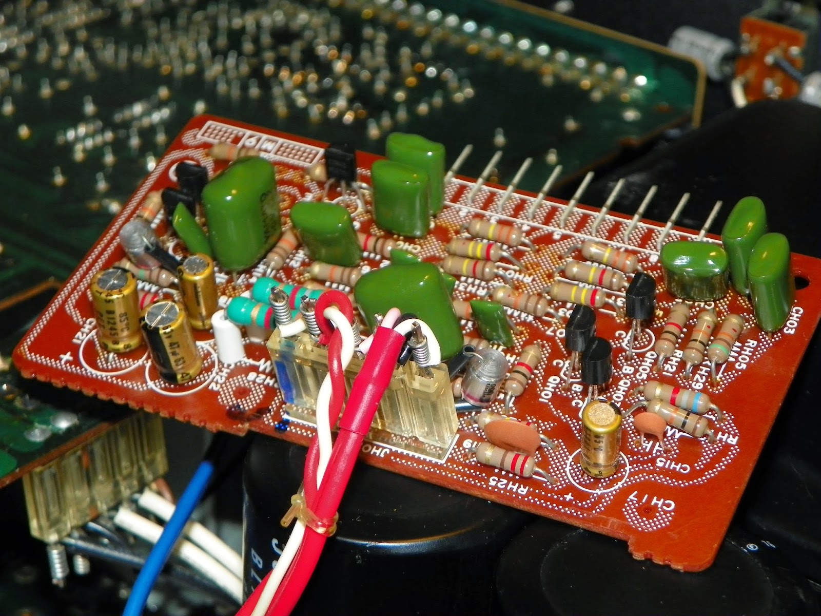


Amplifier
I used some nice Elna Silmic II's and FG's throughout the amplifier stage along with some WIMA MKS2 vie been using exclusively now for all low capacitance locations.  I would like to add we zoo those 700# BJT's here again in the pre-driver pairs. I replaced them again with ksa1220/kscd2690A's respectively. Lots of folks have reported noise from these particular locations. I should add removing the heatsink ank to-3 output bank is easy. Putting the assembly back in is another story….This unit features biasing test pin locations which is always a plus.


Pre/Tone
The input/eq and separate tone control assemblies were recapped using Elna/FG's and more MKS2 films along with a ES BP. Note that one the input/eq PCB has a polar lytic between the pre out and ground tap, also the selector shaft needs to be remove to properly contort the board.  I also ended up removing the entire front chassis assembly to angle the main PCB to an accessible point. 


All in a very robust integrated unit, the silver by the way only came with a outer wood case, no metal enclosures except the pre shielding. The black variant sports a case and rack handles from what I am seeing. 

Sunday, January 11, 2015

Marantz 1152DC Integrated Amplifier Repair

Marantz 1152DC Integrated Amplifier


This unit came in going into protection, also noted was a lack of tone controls and filter modes. Some bench upgrades were done while the unit was opened up including recapping the power supply and amplifier. 


Power Supply
The lyrics here were replaced with Panasonic FC/R and Nichicons, their are also two 133B diodes which are anode cathode series diode in a 3 leg package. I've used UF4005s many time soldering in series and bending to a W, their also a nice MUR1620 TO-220 package replacement available.  Also found was a shorted a Zener in the power supply which was replaced. Its interesting to see there is no regulator adjustment in this circuit.  It also interesting to note all four filter caps are actually wired in parallel, plus the AC/DC mode with the added lyrics across the switch.


Relay
The relay was noted to have a shorted 133B diode and replaced as above along with the QN03-05 BJT(Bi-Polar Transistors), the relay which is a 4dpdt Omron was removed and the contact cleaned. The stand off resistors (1/2W) radiate a lot of heat on the PN00 PCB so I expect many units to so at least minimal charring around RN01/RN09/10.

***Its important to add that RN08 has an incorrect voltage across to Base to Emitter voltages. QN05 B should indicate 1.5VDC wheres as QN04 Emitter voltages should indicate 3.4VDC (5%)+/-


Amplifier 
The entire right channels TO-3 output BJT's were shorted along with several 5.6K resistors shorted and Q721 shorted. 

All the lyrics were replaced with Elna Silmic II and Nichicon capacitors, all the 5.6K and 33 ohm resistors were replaced with a more robust Vishay/BC metal film 1W resistors,  Q721 was replaced and new thermal compound was applied to all 8 heatsink mounted BJT's. Along with both banks of MJ21193/94 ONSEMI outputs with new mica insulators and thermal compound. The only adjustment to note is DC offset, the Bias is pre-determined in the circuit.


***Its important to add that the QT01 BJT Base voltage is NOT tied to the +48 rail supply as indicated.


Filter Amp Assembly
All the lyrics were replaced with Nichicons and all BJT's updated, the location of this board fits into a pin slot not he front panel PCB, to clean the pin connection a pick tool and contact clean is accessible with the faceplate removed.


The 1152DC is very moderately rated, with a single channel at a 4ohm load we noted 144W/CH right before clipping began to plateau, its nominal factory rating is 96W/CH @ 4ohm.

All in im not a fan of the pin connections, some I even remove and solder directly to the PCB pads but for a power amp vs an integrated I would highly recommend!