Wednesday, July 26, 2017

Adam T. and William's Marantz 2275 W/ BA312 MOD Receiver

Marantz 2275 Receiver
**updated to include BA312 modification in 1701#249**


Today were showcasing two Marantz 2275 Receivers that came in from customers for restoration. The Marantz 2275 is one of my personal favorite Marantz receivers from the era. Unlike the popular 2270, the 2275 is built FAR better, with all of the driver issues address. One should compare the 2275 to the 2325 versus the 2270. The 2275 features a robust 26,000MFD filtering, good RF shielding, BA312 IC pre-amp chip AF stage like the 2332 (at/ 18,000MFD)


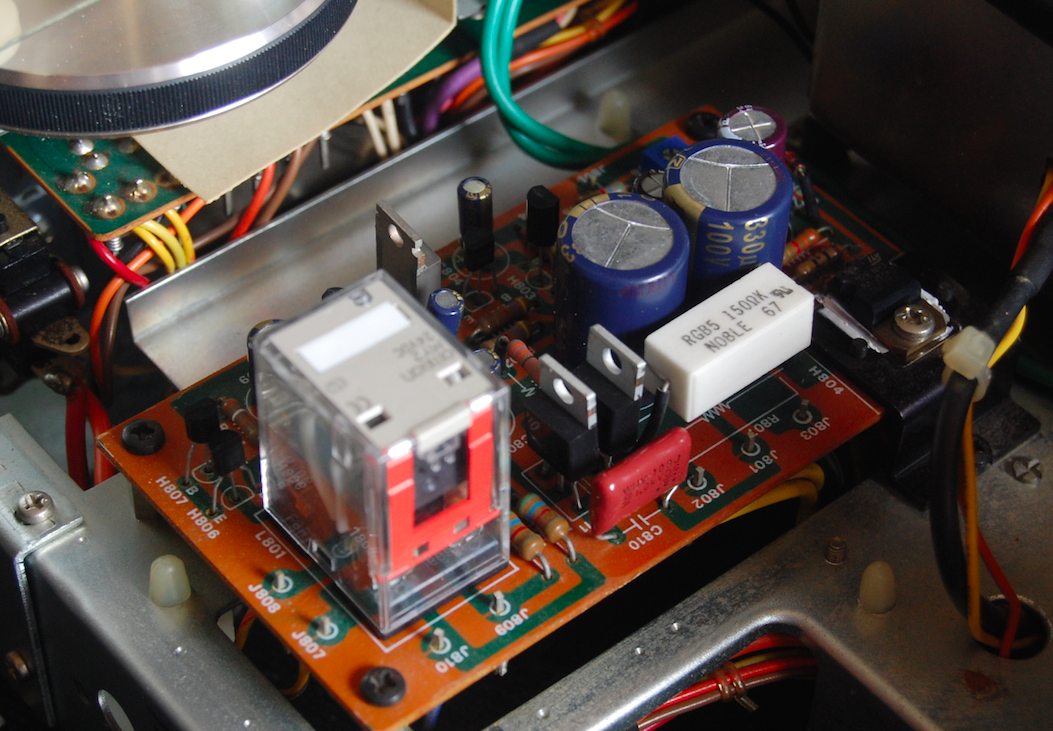
Power Supply / Protection P800
The 2275 features a 11A bridge rectifier output for the driver -/+ 48Vdc rail source. The main RF/AF circuit uses two full wave center tap rectifiers for the protection and 13.4V/35V regulated rail sources.

The two full wave center tap rectifiers were both replaced with state-of-the-art Ultra-Fast (UF) type MUR On-Semi TO-220 type devices, along with the 35V source the initial 220MFD smoothing capacitor was increased to 330MFD, along with all other electrolytic to high temp (105C) long life Panasonic FC and Nichicon PW capacitors with an increase on operating voltages.  High grade WIMA polypropylene bypass capacitors were also installed.   New precision Bourns potentiometers for the adjustment were added along with new low noise Fairchild TO-92 devices and TO-220 Regulators.  Low noise, modern Omron 24V w/ indicators relays were installed.


BEFORE

AFTER


Filter Capacitors
Two new 18,000MFD computer grade Nippon filter capacitors per unit were installed to lower ripple effect and increase loading capacity during low frequency production at increased output levels.


Drivers P700
The 2275 driver section employs a dual differential pair which drivers the output via H703 and predriver/driver H711/12/13 devices per channel with a global feedback circuit and dynamic bias control via H709/10 and a complimentary output stage.

As mapped below the differential pairs were matched within 1% and thermally coupled together, new constant current/ detect, pre drivers were installed using low noise, modern Fairchild TO-92 and TO-126 devices. New general axial Vishay diodes installed as well.  

Differential Mapping


Both potentiometers were removed, soaked, cleaned, lubricated and cleaned, as Ive mentioned several times I very much prefer these large enclosed plastic pots as they tend to be very precise and reliable.  All of the electrolytic capacitors were replaced with audio grade Nichicon KT capacitors with an increase in operating  voltages, all the original circuit films were replaced with high grade MKP, WIMA polypropylene film capacitors.


BEFORE


AFTER


Bias Confirmation

PE01 Tone Stage
The 2275 pre-amp/tone control stage uses a BA312 PRE-AMP IC instead of a differential pair and buffer circuit,  the preceding is a npn/pnp compliment circuit. 

All of the npn/pnp devices were replaced with modern, low noise Fairchild TO-92 devices. 1MFD capacitors were replaced with high grade WIMA polypropylene films along with the initial input films to high grade MKP polypropylene films. Remaining capacitors were replaced with audio grade KT and Fine-Gold Nichicon capacitors including VP BiPolar capacitors with an increase in operating voltages. 


BEFORE

AFTER
W/OUT Modification

W/ BA312 Modification
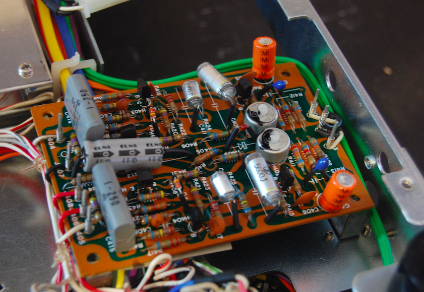

P400 RIAA EQ
The phono stage (RIAA EQ) in the 2275 is a very popular design used in MANY of the 22XX series Marantz units, the RIAA EQ provides a nominal -40dB gain stage using a NPN compliment. One of the known issues with the P400 assemblies is the employment of the 2SC458 transistor which is known to become nosey and failure prone. As shown in the photos below several version of the film compliment were used by Marantz, assuming due to availability/costs at the time of production if no other reason.

All of the npn devices were replaced with modern, low noise Fairchild TO-92 devices including the 458 transistors. The epoxy varistor was replaced with a series of modern axial Vishay diodes. Both clipping adjustments were replaced with Bourns precision trimmers.

The initial input and output coupling films were replaced with high grade polypropylene film capacitors, electrolytic were replaced with a audio grade Nichicon KT type with an increase in operating voltages. 

BEFORE


AFTER


RIAA Curve Response


RF (AM/FM+)
Good shielding encloses both Dolby/FM/AM RF PCB’s to help isolate noise along with the 5-gang tuning capacitor. Sadly one of the original HA1156 IC's due to a bad .47 coupling capacitor.


All of the bipolar/tantalum and electrolytic including a few mylar were all replaced with low impedance, long life Nichicon PW capacitors with an increase in operating voltages as well as high grade WIMA polypropylene film capacitors. 


Hardware
Due to the heat of the original 8V incandescent bulb the vellum paper used to diffuse becomes baked and changes hue along with the meters, its important to replaced both meters and dial display vellum as shown below. Also, new 8V Custom SMD type and LED Bi-Pins installed :)


AUDIO NOTIZEN


Thursday, July 20, 2017

Adam B's Pioneer SX-950 Receiver

Pioneer SX-950 Receiver


Today were showcasing the restoration of a customer Pioneer SX-950 Receiver. As recently posted the SX-950 and SX-850 are very similar with a difference in rail supplies and driver compliments.  Many of the circuit description in this posts are mirror as so from the SX-850 posts recently published. 


Power Supply Board (AWR-101)
Power supplies are one of the most critical areas of a units operation, without a clean and stabile rail source the unit cannot perform optimally.  During this restoration particular attention was paid to significant upgrades done on the power supply.  Using todays modern components we can dramatically update the rectification stages for a MUCH more quite, cleaner and reliable AC/DC conversion. Both of the original 22,000MFD filter capacitors were replaced with a computer grade Nippon 22,000MFD capacitors for an increase in current handling and power reserve and a new 5W 2.7K resistor for the dropping voltage this established the 49.5V rails versus the 45V 80mA rails at idle on the SX-850.

The SX-950 uses a 1A Full Wave Centre Tap, 1A bridge and 3A bridge rectification for the established  -/+ 60/63V and -/+45V rails.  The Full Wave Centre tap rectification was replaced with two robust, Ultra-Fast low switching noise On-Semi MUR TO-220 rectifiers and a WIMA polypropylene bypass. The 1A bridge rectification was replaced with a custom PCB populated with again Ultra-Fast, uber low noise axial Fairchild rectifiers and the 3A bridge rectifier was rebuild, again on a custom PCB populated with On-Semi TO-220 type Schottky rectifiers. The resulting product is an incredibly clean, fast and low transient AC/DC conversion which made DRAMATIC effects on the over presentation of this. This has been one of the most impactful upgrades I’ve notated to date for the record short of low noise, better 1st-4th order driver upgrades. 


-/+50/49.5VDC RAILS

The remaining devices and voltage regulators were all replaced with modern, robust Fairchild TO-220 regulators, Fairchild TO-92L and TO-126 devices for better dissipation.  The original electrolytic capacitors were all replaced with a high temp (105C) Panasonic FC and Nichicon PW with an increase in operating voltages. 


BEFORE


AFTER

Protection Board (AWM-062)
The Relay to the SX-950 is a chassis mounted 24V device, the original case is retain due to the odd mounting pattern and wired directly in circuit.  The electrolytic on this assembly are known to become leaky and fail in circuit causing a random dis-energize cycle from the timing capacitor.  The protection incorporates a overload and short detection. 

This SX-950 came in with a fault detected at the timing capacitor that had excessive leaking upon test causing the relay to energize and de-energize/time. The electrolytic capacitors were replaced with a high temp (105C) Panasonic FC and Nichicon PW  capacitors with an increase in operating voltages. Two .22MFD WIMA  high grade polypropylene film capacitors were installed.  All of the transistors were replaced with better dissipating, robust TO-126 and TO-92L modern Fairchild devices.


BEFORE


AFTER

Power Amp Board (AWH-059)
The SX-850 and 950 share almost identical driver stages, short of the increase rail voltages and more robust output devices on the SX-950. The SX-950 uses a compliment of X8 NPN/PNP 2SB557/2SD427 TO-3 devices instead the lower output  2SD371/2SB531 devices on the SX-850 and the rail supply. (see filter capacitor description above)

The initial differential pair transistors were matched within 1-2% as shown below in their respective curve mapping.  Current, Pre-driver and Driver devices were all updated with modern, low noise TO-126 and TO-92 Fairchild devices. 


New precision Bourns potentiometers were installed for adjustments and several Fairchild axial diode array.  Electrolytic capacitors were all replaced with a low impedance, high temp (105C) Nichicon PW and audio grade Nichicon KT capacitors with an increase in operating voltages. 


BEFORE


AFTER


Bias Confirmation

Equalizer Amp Board (AWF-011)
Two versions of the RIAA stage are known in the SX-850/950 series with only slight differences in the AF stage. The original PNP compliment populated are known to develop some noise associated issues. This SX-950 used the non-B version lacking additional 100MFD capacitors.

All of the low signal devices were replaced with TO-92/TO-92L low noise, modern Fairchild devices for a significant reduction in hum noise. The electrolytic capacitors were all replaced with a audio grade Nichicon Fine-Gold and KT along with low impedance Nichicon PW capacitors with an increase in operating voltages. A slight modification to the NFB was integrated. Below is the RIAA Curve response of the SX-950 which is even more accurate than the SX-850 I just did. Extremely sharp standard curve :)


BEFORE


AFTER

RIAA Curve Response (2.5mV 47K @ 31.5Hz-15Khz)

Flat Amp Board (AWG-038), Tone Amp Board (AWG-039) and Switch Assembly Board (AWS-094)
The SX-950 uses a NFB centered circuit with a 2stage direct coupled gain stage and a 2Sk30 JFET per channel, the resulting frequency response is very suitable with only a deviation of -0.5%dB. The Tone control assembly has a variable Bass and Treble control a tone defeat is employed as well.

All of the electrolytic capacitors on both assemblies were replaced with a Nichicon Fine-Gold and KT audio grade along with a low impedance Nichicon PW with an increase in operating voltages. High grade WIMA polypropylene film capacitors were installed as well.  The major difference is evident in the Tone Amp PCB AWG-039 where the additional 2.2MFD capacitors are replaced with a 10MFD size. All small signal transistors were replaced with a low noise, modern TO-92/TO-92L type Fairchild devices and new Vishay general axial diodes. 


BEFORE AWG-038


AFTER


BEFORE AWG-039


AFTER


Hardware

New LED’s installed to give it a more cleaner, define glow across the dial using custom SMD warm white LED’s along with new LED indicator lamps. 


AUDIO NOTIZEN