Here we have two very clean Sansui AU-717 Integrated Amplifiers that came in for a restoration. The AU-717 and matching TU-717 Tuner remain one of the most popular Sansui combinations still today! The AU-717 features a unique approach by Sansui at the time and a turn in more expensive construction that the related G or 8080/9090 series receivers. The AU-717 utilizes a dual monolithic power supply with separated transformers for a mono block topology and a DC Push-Pull driver stage and a combined filtering of 60,000 microfarads!


Power Supply F-2663 and Filtering Capacitors
The main F-2263 assembly is used for the monolithic power supply and protection detection circuits. As describe the AU-717 uses two separate power transformers and dual bridge rectifications stage coupled with two per side 15,000MFD filter capacitors. The caustic glue issues is highlighted below. All of the electrolytic were replaced with high temp (105C) long life FC Panasonic and Nichicon PW capacitors with an increase in operating voltages. The Bi polars and .47 coupled electrolytic were replaced with Nichicon VP and high grade WIMA MKP film capacitors. All of the diode bridge 10D1 and 2473 were replaced with Fairchild 4148 and Ultra-Fast UF400# type diodes, all VD1212 type epoxy diodes were replaced with series Fairchild 4148 diodes.


All of the TO-220 voltage regulators which tend to show signs of excessive heat are replaced with heavy duty OnSemi MJE TO-220 devices and thermal compound applied. The relay was replaced with a heavy duty low noise type Omron MY4 relay. Due to excessive glue damage about 15 carbon film resistors were replaced with KOA carbon film resistors. The solder joints due to excessive heat were reflowed as well.
BEFORE

AFTER


The Sansui Caustic Glue & Fusible Resistor Saga
One of the more infamous vintage audio equipment conundrums involve how Sansui’s were manufactured and component selection. During the manufacture process large vertical axial electrolytic capacitors were affixed to the PCB using a glue, like most manufactures. The differences occur over time, as many of the Sansui’s are now decades old we are finding that the glue used on large capacitor has become caustic and oxidized, as we know oxidized material also become conductive! The glue was loosely spread and often covers multiple components nearby the large capacitors resulting in what can be expected as systemic random failures in Sansui’s. Another point of contention is the use of a Fusible resistor which exhibit two odd characteristics; the insulation of the resistive body lends to premature drift in high heat environments and the failure mode of the substrate tends to fuse rather than open the circuit which leads to excise current consumption of the stage and cascade failures throughout the driver stage etc.
BEFORE


AFTER


15Kmfd Filter Capacitors
Each stage uses two 15,000MFD filter capacitors with a 2.2MFD bypass film across. High Temp(105C) low ESR Cornell type 15,000MFD/100V capacitors were installed with high grade MKP Solen 2.2MFD film capacitors to bypass.
OLD

NEW


Filter Capacitor audio grade Solen 2.2 bypass film capacitors installed

Drivers F-2721 & F-2722
The AU-717, like many Sansui’s uses a dual JFET 2Sk97 device for the initial differential stage to establish the zero drift dc deviation circuit along with a push-pull front end and NPN/PNP Darlington output stage configuration.
Unfortunately like the F-2663 assembly it also has the caustic glue abound…below is after scrubbing the material off and cleaning the PCB.

All of the electrolytic were replaced with low impedance high temp (105C) Nichicon PW’s and audio grade KT with an increase in operating voltages. The 1MFD was replaced with a high grade WIMA polypropylene film capacitor. The 22V zener’s were replaced with a Fairchild axial diode and the 150 ohm fusible resistors were replaced with a KOA carbon film 1/2W.


The tier differential NPN stage and problematic 2SA750 transistors were replaced with a low noise TO-92 Fairchild transistors Beta matched within 1%. The complimentary pre-drivers were replaced with low noise robust TO-126 Fairchild transistors.
BEFORE

AFTER


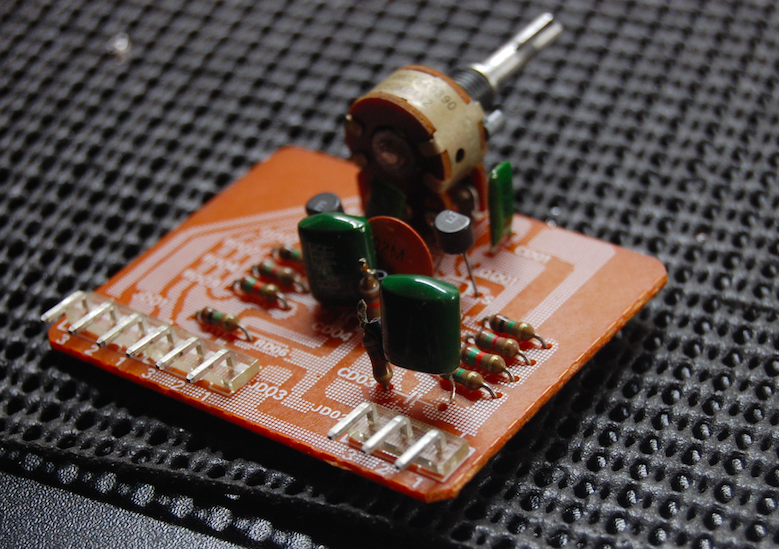
Pre-Amplifier/Tone F-2720
One of the best components on the AU-717 is the calibrated stepped potted attenuator used for gain control, it has a smooth and precise control to it. The pre-amp is a PNP gain stage BJT compliment pre-amp with a capacitor coupled Main/Out output function.


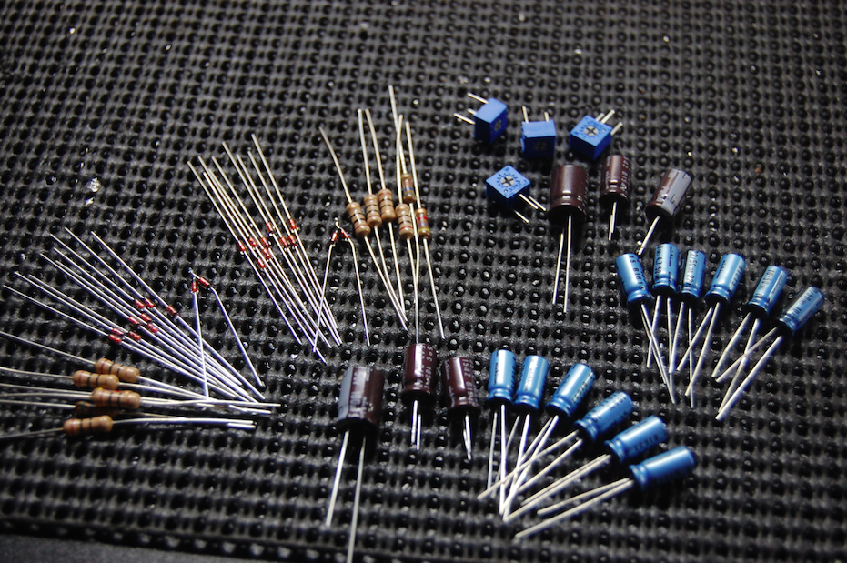
All of the electrolytic capacitors were replaced with low impedance long life Nichicon PW and audio grade Nichicon KT capacitors with an increase in operating voltages. The original .33 and .47 films were replaced with high grade WIMA polypropylene and Solen MKP polypropylene film capacitors.


The 82ohm fusible resistors were replaced with KOA carbon film 1/2W resistors along with the VD1212 epoxy diodes to Fairchild 4148 series axial diodes. All of the low signal BJT were replaced with Fairchild TO-92 low noise transistors with the PNP gain stage to a 1% matched BETA.
BEFORE


AFTER


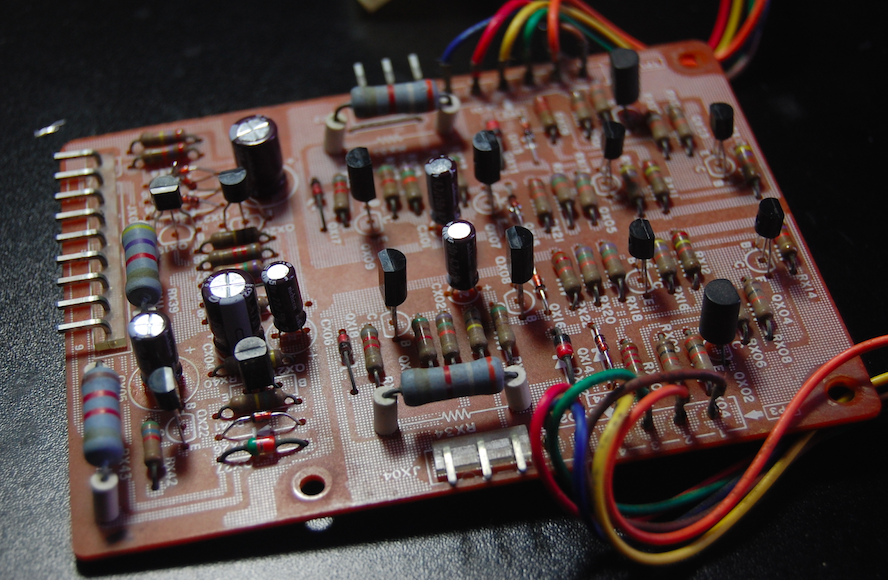
RIAA EQ F-2723
The RIAA stage like the front end AF stage above is shielded at the chassis which is a nice addition to see in a quality integrated amplifier. Like the AF stage, it uses a PNP differential gain driver stage. The input coupling films were replaced with high grade Solen MKP polypropylene film capacitors. Remaining electrolytics were replaced with a low impedance Nichicon PW and audio grade KT with an increase in operating voltages.


As above the 82 ohm fusible were replaced with a KOA carbon film 1/2W resistors along with the VD1212 epoxy diodes to Fairchild 4148 series axial diodes. The differential gain stage and problematic 2SA726 (7## series) were all replaced with a low noise TO-92 Fairchild transistors with the differentials matched to a 1% BETA.
BEFORE

AFTER


Audio Notizen