Friday, October 27, 2017

Steve's Yamaha C-4 Pre and M-2 Power Amplifiers

Yamaha C-4 and M-2


Today were showcasing a customers two Yamaha’s…the M-2 Power Amplifier and C-4 Pre-Amplifier.  The M-2 I hold as one of my personal top favorite amplifiers…featuring incredible build quality and performance you don’t see under $5K typically.  The C-4 is a perfectly matching pre-amplifier, with specs to match and beat most pre-amplifiers on the market…and incredibly linear response output!


Yamaha C-4 Pre-Amplifier 
The C-4, released from 1979 to 1981 was Yamaha’s upgraded version of the C-1/C2 pre-amplifiers with cartridge loading features.  The C-2 employs a robust  dual FET RIAA amplifier stage, quality independent headphone amplifier, line level output with incredible S/N, frequency response and total harmonic distortion levels. 

NA07153 PS
The C-4 uses a dual bridge rectifier array for the 12 and 45-/+ rail sources, each were replaced with a ultra-fast, soft recovery  axial Vishay Diode arrays. The initial filtering stage capacitors were replaced with a high temp (105C) low impedance Nichicon PW type with some capacitor values increased for better filter and all operating voltages increased.  Associated regulators were all replaced with a robust TO-220 On-Semi device with  synthetic Wakefield compound applied and remounted. 


Flat Amp Stage/HP
The line stage amplifiers are separated into several gain/application stages across the main PCB. The various differential stages were Beta matched and replaced with low noise T)-92 Fairchild devices and TO-126 devices for better dissipation due to the high heat environment of the C-4.  The Yamaha branded film capacitors were all replaced with high grade MKP Solen polypropylene film capacitors and WIMA polypropylene films. Nichicon Audio grade KT and Muse BP capacitors were installed with an increase in operating voltages. 

The Headphone amplifier is its own independent stage capable of driving various loads (though watch out more heat!) The initial differentials were matched and replaced with  low noise modern TO-92 Fairchild devices. The VD diodes were replaced with modern 4148 Vishay axial general type.  Electrolytic’s were replaced with Audio grade KT and low impedance Nichicon PW’s with an increase in operating voltages.


RIAA EQ NA07149
The C-4 allows for both MM and with the new cartridge loading feature an easily integrated MC amplifiers. With a dual FET differential and loading switch the RIAA is incredibly accurate to the standards at the time and a impressive dynamic margin of 285mV (kHz .01%)

The house branded films were replaced with a high grade MKP Solen polypropylene film capacitor and polypropylene WIMA film capacitors. The electrolytic were replaced with Vp and KT audio grade Nichicon capacitors with an increase in operating voltages. 


Hardware
Like most in this series and as discussed below, the 14V lamps tend to fail quickly in these Yamaha’s, all the original lamps are replaced with a long rated LED equivalent…also no more hot buttons ;)


Audio Notizen


Yamaha M-2 Power Amplifier 
Produced from 1979 to 1982 the M-2 was rated at a minimal of 240W at an impressive 0.004%THD (8ohm) the M-2 is a DC array with a OCL /triple push pull output complimentary stage. 

Pre-Driver & -/+ 80V Supply NA07311
One of the unique features of Yamaha M-2 is the driver design. The Pre-Driver stage was separated from  the final driver stage utilizing a different PCB footprint. The Pre-Driver is mounted with a divider shield  to the NA07314 assembly for extra noise reduction and disperse interference potential. This stage also helps regulated the -/+80V source for the amplifiers. The VAS stage below is a tiered cascade circuit employing a Dual FET input and a cascade bootstrap circuit, current mirror and PP output.

All of the original Yamaha branded house capacitors were replaced with a high grade MKP Solen Polypropylene film capacitors with .1MFD WIMA polypropylene bypass capacitors.  Nichicon PW and High temp (105C) electrolytic capacitors with an increase in operating voltages were installed replacing the original worn out electrolytic. Additional new .1MFD WIMA high grade polypropylene were installed as well.  The CD type diodes were all replaced with tied general 4148 axial Vishay diodes. Several of the heat prone 33K resistors were replaced with a 1/2Watt Carbon Film type for better dissipation. 


Differential pairs (including current mirror) were matched and installed with low noise modern TO-92 Fairchild devices. Both TO-220 pre-Drivers were replaced with modern, heavy duty TO-220 Fairchild devices thermally coupled with new performance synthetic Wakefield compound.  New precision Bourns -/+ Voltage adjustment potentiometers were installed.
BEFORE

AFTER


Driver NA07314
The final driver assembly is mounted parallel, and under the Pre-Driver assembly above. Mounted with heavy copper busses and even TO-3 copper mounting hardware, the TO-3 output banks utilize a heavy powder coated cage as well. The Emitter resistors are fixed via heavy solder mask to the TO-3 mounts using heavy duty sub-chassis mount type wire-wounds. coupled to the above VAS stage the driver uses a three stage emitter output (OCL SEPP) with a high bandwidth output device stage. 

New high grade MKP Solen polypropylene film capacitors were installed as well as high grade WIMA polypropylene films.  Capacitors were replaced with high temp (105C) Nichicon PW low impedance type with an increase in operating voltages. The Bias adjustment was replaced with a precision Bourns potentiometer. Constant current loads were replaced with modern, reliable TO-126 Fairchild devices. 

BEFORE

AFTER


The Outputs were removed, each beta tested and new performance synthetic Wakefield compound applied and remounted. 


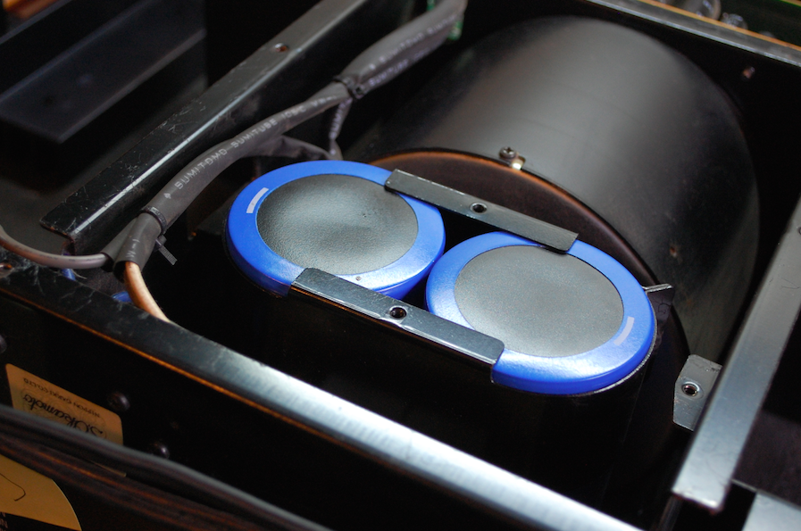
New 22,000/100V Computer Grade, high quality Nippon Filter Capacitors were installed.


Hardware Upgrades
New LED’s were installed for the original lamps, the originals being 14V small wheat type often burn out as the voltage application is far too high for any decent life span.


New high quality 5-Way Insulated W/ Gold Plated Binding posts were installed replacing the original cumbersome and frail plastic binding posts.


BEFORE


AFTER


Audio Notizen


Sunday, October 22, 2017

Ed's Sansui AU-999 (With Pre-Amp Modifications)

Sansui AU-999


The Sansui AU-999 integrated amplifier was amongst one of Sansui’s early transistorized components after the tube era. The AU-999 was a first as it truly tailored its design and function for the budding audiophile. With heavy Mylar use, precision tone controls with fixed indents, separation features (with a active crossover in mind as well) Full PNP Pre-Amp with a DC priority Power Amp and to top it off..one of the most aesthetically pleasing units Ive ever come across.


The AU-999 does however…lack some emphasis in the mid range presentation, luckily a well known technician had worked closely with a engineer friend of his to implement the modifications outline below which really bring the AU-999 to contender status and fatiguing into bliss!


F-1230 Main PS Full Wave Centre Tap Rails
The power supply for the 999 is separated into three arrays a, the F-1230 as a  Full Wave Centre tap for the -27/25V source and two -/+ 42 Sources.  The full wave diode array was replaced with a modern On-Semi TO-220 Ultra-Fast soft recovery common anode device for quite transients. The initial decoupling capacitors were increased from 220 to 330MFD for better filtering of the DC source. All of the electrolytic capacitors were replaced with high temp (105C) long life and low impedance Panasonic FC and Nichicon PW’s with an increase in operating voltages.   


BEFORE

AFTER


F-1231 & F-1277 Full Bridge Rails -/+
The 999 designed two separate isolated windings for the driver rails establishing a -/+42V source. Using a shared 3A bridge rectifier and a pair of 4700MFD capacitors. When this unit arrived the capacitors had been cut and removed and the the filter mounts missing. New Cornell 6800MFD capacitors were installed and mounted under the chassis well in the rear of the unit very discretely. 

The regulating 8002 devices were both replaced with a low noise modern On-Semi MJE TO-126 device for better dissipation and reliability. The bypass capacitors were replaced with a high grade WIMA polypropylene type and remaining electrolytic to a low impedance, high temp (105C) Nichicon PW capacitor with an increase in operating voltages. 


BEFORE

AFTER


Its noted this is also the Bias base using two 0.5ohm emitter resistors. The SM indicates a bias of about 30mA,which typical for a Class AB type SS amp,  though I hate this method as converting to a DC emitter voltage is easier.  (.5OHMX3mA=15mV vice versa)

Bias Verification


F-1209 Pre-Amp & SubSonic Delete
 One of the highlighted modifications for cleaning up the signal line attenuation is removing the sub-sonic filter circuit between the pre-amp output and driver inputs. This is removed and the input wire now directly soldered to the card slots. All of the BJT's in the Pre/RIAA and Block circuit were removed and replaced with a low noise modern TO-92 Fairchild device.

The F-1209 is a fully PNP compliment gain stage, very simple in design with some gain shortcomings address below; For this board all of the small signal devices were replaced with modern low noise TO-92 Fairchild devices. The mylar films were all replaced with a high grade polypropylene film capacitor and high grade WIMA polypropylene films.  Nichicon KT Audio grade were used in the remaining locations with a increase in operating voltages.  See the additional Modifications and performance report evaluations of the modifications below!


BEFORE

AFTER


Sansui AU-999 Modifications
A couple years ago a forum member by the handle of Kevzep worked with a friend to establish a pre-amp and Bass EQ modification for the Sansui AU-999. The AU-999 in its original design has the pre-amp lacking sufficient gain for the driver output causing premature oscillation/distortion and a very empty and poor middle spectrum presentation. After doing some decent raw listening I am very much inclined to agree it just lacks any definition in the mid bandwidth output.  The Pre-Amp mods addressed below add a sustain gain increase to the Pre-Amp output with notable lower distortion allowing for a more fulfilled output, in conjunction with the Bass EQ modification to increase the overall boost (15dB) and general subsonic enhancement.  For a quite some time I refrained from performing the modifications as their was no initial reports to conclude their findings, I’ve taken the liberty here to do a before and after comparison of the F-1209 Pre-Amp modification changes (Defeated Controls-Fix Line)  My listening impression is greatly improved after the modifications were performed…the overall stage is more lush and deeper with some tone now present in the middle spectrum sound (2Khz+) making what was before a fatiguing listening experience now enjoyable. Kudo’s to Kevzep for his work on this modification and publishing the details. I hope these tests help! Schematic/Modification Credits: Kevin Bennett


F-1209 Pre-Amp Cards
After the initial rebuild of the F-1209 assembly a series of tests were performed to establish a base set of parameters to judge the modification improvements.  Afterwards several resistors are replaced on the assembly or omitted to establish the increase in gain output.


Additionally the Bass EQ modification includes changing the preexisting resistor values on the selector gangs to a 1Megaohm and 2.2K Ohm resistors.


F-1159 Drivers & F-1334 Delete
The original F-1334 crowbar protection circuit is removed from the unit and inline fuses left employed for safety and protection methods as the original tends to fail and cause more problems than help.

Removed Sub-Sonic + Protection circuits

The drivers are comprised of a common emitter differential stage and current type mirror/reg. with a tiered pre-driver/driver voltage/current gains stages.

The electrolytic capacitors were replaced with a Audio grade JT and VP Bipolar Nichicon capacitors with an increase in operating voltages. The input coupling was replaced with a 1MFD MKP polypropylene high grade film capacitors. The original axial diodes were replaced with a modern general Vishay axial 4148 type.  New precision Bourns adjustments were installed replacing the open-frame potentiometers. 


BEFORE

AFTER


The differential pairs were matched within 1-5% using TO-92 low noise Fairchild devices. The remaining current mirror/ pre-driver were all updated with either Zetek and low noise T-126 Fairchild devices.  One side had VERY mismatched outputs on the right channel which were replaced with modern TO-3 MX003 type devices with new performance Wakefield thermal compound. In all the AF stages ALL PNO saucer


Beta Mapping


F-1208 Filter Block
Preceding the pre-amp stage and the line gain controls is the F-1208 Filter block circuit. All of the small signal devices were replaced with a modern low noise TO-92 Fairchild devices. Electrolytic capacitors were replaced with a Audio grade Nichicon KT with an increase in operating voltages. The mylar were all replaced with a high grade polypropylene and WIMA polypropylene film capacitors. 


BEFORE

AFTER


F-1228 RIAA Phono
The phono stage is comprised of a simple PNP/NPN gain stage. The original design utilizes a very noisy and failure prone 2SC458 device which was replaced along with remaining devices with a modern low noise TO-92 Fairchild device. The electrolytic were replaced with a Audio grade Nichicon KT with an increase in operating voltages. The input/output coupling capacitors were replaced with a high grade polypropylene film capacitor.


BEFORE

AFTER


Audio Notizen