Thursday, April 28, 2016

Pioneer SX-550 Receiver Highlight

Pioneer SX-550 Receiver


We have a little Pioneer SX-550 Receiver in today, thought we'd show some highlights. Produced for a limited run from 1977 to 77" its features a 3 gang tuning capacitor and modest 20W rated output. The 550 was the entry class for many SX users because of its price point.


Switch/Repair & Modification
One of the common issues with the lower series SX Pioneer's is the integrated Power/Speaker Selector switch. Both sections of the phenolic based speaker switch and integrated power switch are prone to excessive carbon build up and then AC arching. often presenting as fluctuating AC/ flicker lamps. If you place you ear near (*caution...) you can actually hear the arching.


One fix is to tear down the switch and phenolic assembly by desolder and removing the unit. As photo'd below its important to scour and clean the contact points and clean and treat with a high quality non residue cleaner.


In some cases, such as this.... no matter how much cleaning occurs the switch is done for.  In that case I recommend salvaging and cleaning the speaker selector and we did and adding a new power switch to the rear of the chassis for discrete mounting. A 5A DPDT single throw was chosen for this unit with a Vishay X1Y2 safety capacitor installed parallel the switch.


New multi-facet LED's were installed along with a LED function indicators. to give off a new clean/ white glow!


Audio Notiz
The resulting verification report was as expected with a slight deviation in the low frequency to sub-sonic frequency response at 10Hz to 35Hz with a noted deviation of +1dB.


Tuesday, April 26, 2016

Kenwood Model 600 Supreme Series

Kenwood Model 600 Supreme 


Here is another Kenwood Model 600 Supreme we have in for a restoration. The Kenwood 600 is a TOTL variant quietly produced and exported by kenwood-trio. part of the infamous Supreme series, manufactured from 1973 to 1979’ this features the popular dual power supply topography designed by kenwood and later adopted with Kentronics which later produced the Accuphase series. From research it would indicate that their are potentially less than the 1500 or so 600’s out there produced and who knows how many left in good repair.


With an impressive 18,000MFD of filter a side for a total of 72,000MFD of reserve!, the 600 also touts a limited ALPS 44 stepped attenuator and a ALPS coaxial balance fader! The 600 used excessive heatsink platforms and specific shielding channels for input/output leads along with bottom chassis well.


Power Supply X00-1720-10 & Protection X00-1700-20
The dual mono power supply assembly is a slide connected PCB into a molex base at the chassis, supplied with independent 18,000MFD caps.  The electrolytic were all replaced with a high temp (105C) long life Nichicon PW and Panasonic FR/FC type with VP 100MFD bi polar capacitors.
Through several variations I was able to correct the 40/28 and 14V output voltages by updating the 2sc1419/2sa755 BJT’s to heavy duty On Semi MJ15/32/33 type TO-220 transistors along with their TO-92 pairs of KSA992/KSC1845 type. 
BEFORE


Noted dZ5-9 were updated to general type 1N4148 diodes and the V06B type diode at Dz10 updated to a ultra-fast 4005 type diode. I want to also note that the glue used for the large original 100MFD caps had severally corroded the diode at Dz10 and associated resistors which had to be replaced.

AFTER


The ProtectionPCB is a dual facet over current detection and excessive offset detection.  Protection transistors Q9-11 were all updated to 733/1845 BJT’s. I want to note that pinout for Qz9/10 (733/1845) are different than the PCB topography. Qz11 was updated to a KSC6909AYS class (2SD415) and a new Omron MY2-24V was installed.


The original four 18,000MFD filter capacitors were replaced with a high quality Nippon Chem-Con 18K 75V filter capacitors with adapted screw terminations.

Originals...

New Nippon 18Kmfd


Amplifier Stages X07-1440-00
The driver stage consists of an initial 1st order dual FET package IC differential 2SK58, which is enclosed in its own shielding!, the proceeding second stage differential is comprised of a pair of NPN transistors (front end gain bump). The 2nd order differential were swapped with 1% matched ZTX694 bjt’s (All BJT’s watch pinout*) and 3rd order differentiate KSA1381 type. Major upgrades to the transistor packages should be done as we did here due to their high failure rate at Q6 (2sc1452) to a KSC3503 for the constant current BJT.


All the original bias and especially the offset course/fine post should be replaced, we choose a high quality Bourns precisions multi turn trimmer. All the electrolytic capacitors were replaced with a audio grade  Nichicon KA (10MFD) the remaining films were replaced with a high grade WIMA polypropylene .1MFD and a Panasonic ECW high grade polypropylene .01MFD capacitors. One of the prized components in the driver stage is the TO-3s were Sanken 1164/747A output devices capable of a 40A drive(PVP)!, which were removed and MICA/compound applied.


Pre-Amplifier (RIAA) X08-1560-10, Tone Control X11-1310-00 & Filter Assembly X12-1130-10
Unique to the technilogical advances prevalent within the 600, the RIAA stage is comprised entirely of  JFET devices. In a 3rd order array the initial FET’s comprise of a Class A differential + drive stage with a constant current regulation.  All the original electrolytic were replaced with audio grade Nichicon KA and Fine-Gold capacitors, while 1MFD< were replaced with high grade WIMA polypropylene film capacitors. 


The tone stage is designed again around a class front end, using a Shunt-Regulated-Push-Pull (SRPP) configuration using  FET’s. (2SK Japanese devices) The Tone and filter assemblies were treated as above, with all electrolytics replaced with audio grade Nichicon KA and high grade WIMA polypropylene film capacitors. The input stage of the filter assembly had the original mylar/poly films upgrade to high grade Panasonic ECW polypropylene type. 


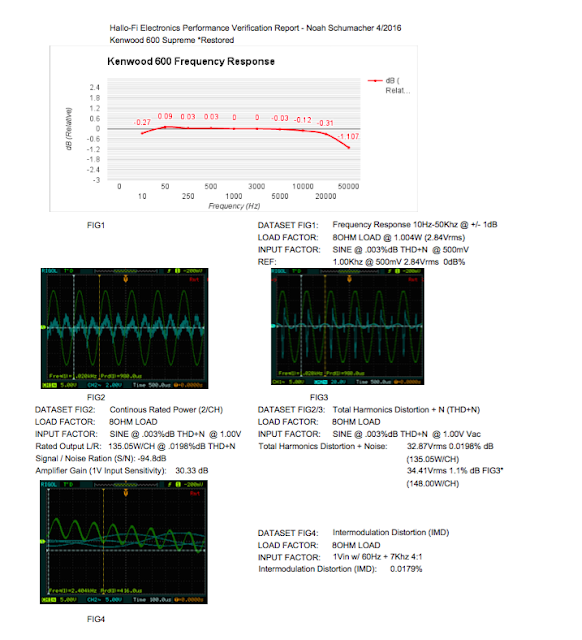
Verification Report 4/8 OHM Reports


Saturday, April 16, 2016

Marantz 2230 Receiver Restoration

Marantz 2230 Receiver 

Today were showcasing another Marantz 2230 Receiver restoration! One of my absolute favorite Marantz receivers with looks to go, the Bleu LED’s we install in these turn out phenomenal. 


"Best in its class. With impressive specifications and Marantz-exclusive features, the Model 2230 offers more value and performance than any other receiver in its class. We've known that for years. But just recently, one of the nation's most respected independent consumer testing organizations verified it. In not one, but two separate categories -- featuresand performance. It delivers 60 Watts continuous power, both channels driven, from 20 Hz to 20 kHz with total harmonic and inter-modulation distortion well under 0.5%. Stepped, three-zone tone controls for BASS, MID, TREBLE. Provisions for tape decks, phones, record changers and 4-channel adaptors. Ultra low-distortion FET, RF and IF circuitry. Massive heat sinks; automatic protection for internal circuitry and associated speakers, plus the famous Marantz gold-anodized front panel. Looking for a moderately priced receiver? The Marantz 2230 out-does them all."

- excerpted from a 1973 Marantz stereo equipment catalog


Power Supply P800
The regulated 30V power supply is a simple design supplying 66V rails for the drivers and 14/35.6V for the auxiliary assemblies.  All of the electrolytic capacitors were replaced with a high temp (105C) long life Panasonic FR/FC capacitor, The original 2SC1213 NPN transistor was replaced with a modern TO-92L KSC2383 BJT along with the 14V /500mW zener at H806. The mounting glue is etched off as well, the noted 30V TP is at J808. The original filter capacitor was upgraded to a low ESR long life 10,000MFD capacitor and both coupling capacitors upgraded to two low ESR, long life 6800MFD capacitors. A new 7A DPDT power switch and Vishay X1Y2 safety capacitor was installed as well.


P400 Pre-Amplifier
I decided to try some very nice Solen polypropylenes on this stage and the phono to replace with original polypropylene films. I think the the MPK Solen is an incredibly film, cost appropriate yet ever bit as good as the EVO Oil’s we’ve tried extensively.   The remaining electrolytic were replaced with audio grade Nichicon KA/ Fine-Gold series. Per our protocol all 1MFD (AF) stage caps were replaced with a high grade WIMA polypropylene film capacitor. The P400 is designed around a small signal BJT complimentary gain driver stage with variable bass/mid/high attenuations. This same topography is seen in MANY of the 22XX series such as the 2245/70.


BEFORE


AFTER


P700 RIAA/PHONO
The phono stage is in the 2230 is one of the best, bar none. With a nominal Av of 40dB its more than enough drive. Their are some major updates this assembly needs though. The notorious 2SC458 transistors are well known to break down under load with pre-emptive failure and potential noise floor issues, these were replaced with 1% matched Hfe 1845 BJT’s. The original tantalums were replaced with a audio grade Nichicon KA capacitor and Fine Gold 100MFD Nichicon. The original films were again replaced with a high grade Solen MPK polypropylene film capacitors. The original VD glass pack diodes were also replaced with tH709 constructed of two 4148 diodes in series and 708/707H single 1N4148 diodes. 


P750 Driver Assembly
I’ve always been a huge fan of the 2230 topography, very simply push-pull design thats tried and true, very stabile and reliable unlike the 2270. Using a single H751 as a gain drivers to the H752 down to the 3rd order devices. It employs a integrated current limiting protection of the output devices through a current deviation circuit.


All the electorlytics above 1MFD were replaced with a audio grade Nichicon KA and Fine Gold, the 1MFD pre-driver coupling capacitor was replaced with a high grade WIMA polypropylene film capacitors along with a 100PF  WIMA polypropylene at the input capacitor C761. The output coupling C760 .1 MFD film was replaced with a high grade MKS PP WIMA film capacitor as well.  Both Bias and clipping potentiometers were replaced with precision tolerance Bourns pots. new thermal compound was applied to the outputs and thermal tracking diode H005 SV-3A. Its very important to update the glass pack at H757 S3016R with a general 4148 diode for reliability. 


I want to take a special focus on the before and after verification reports, the results are tremendous! Lowered total THD+N response, more linear frequency response at the peak sub sonic and ultra high frequencies, about 3 watts gained with an even better intermodulation response (4:1 60hz/7Khz)


BEFORE Restoration


AFTER Restoration