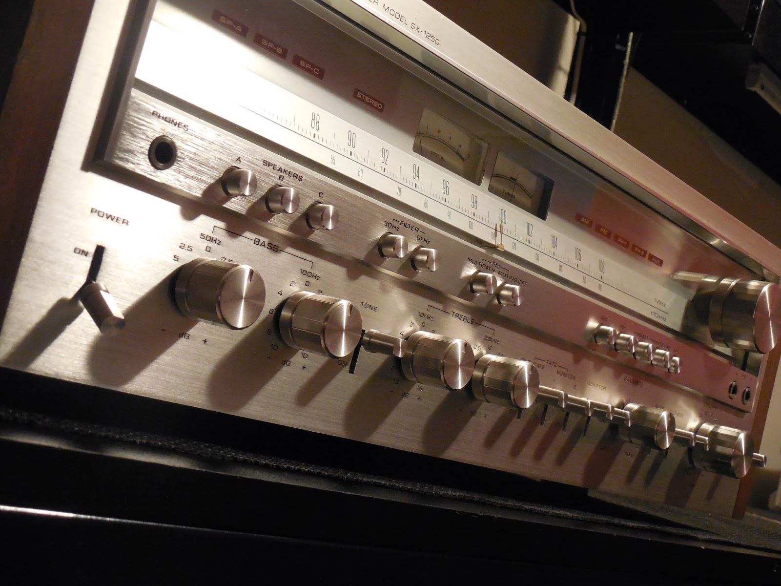
Two Pioneer SX-1250 Receiver's
Here we have two Pioneer SX-1250 Receivers. One unit came in with blowing fuses and required a little extra attention. This particular unit received new OnSemi TO-3 output devices and 3rd order drivers, as such we were able to obtain a final harmonics distortion and a slight increase in performance with original biasing.
Stabilizer AWR-106 and Power Supply AWR-107
The SX-1250 features a potted toroidal power transformer with no discernible slew inductance and isolations tied to separated bridge rectifiers. Also integrated is a reserve of 44,000 microfarads per side! The original capacitors all reflected signs of venting at the terminal junctions.
The filter caps provide some of the most critical paths in the receiver to provide filter smoothing and power reserve for the push-pull operation at all frequencies. For comparison we may see 25Vrms at kHz but at 20Khz that may extend to -/+ at 30Vrms or drop at sub sonic frequencies so these couplings are paramount for optimal operation.
Also noted, one of the units had a small 22K/80V filter capacitor installed from a prior repair somewhere, unfortunately they cut the original bracket down so some improvising was due. The new 22,000/100V Nippon filter capacitors were installed in each unit, a new 50-60mm clamp was secured and tapped under the original clamp for a clean flush look.
InRush Current Notation**
The SX-1250 also employs a 48V LS soft start relay to limit the large inrush current attributed from the low inductance to high 22K filter caps, this charge period can generate several hundred amperes, a large limiting 30W resistor thermal coupled to a thermal fuse triggers the array. The housing was removed which is a chassis mount and points brandished.
AWR-107 Power Supply
The power supply is initially comprised of two 470MFD axial capacitors. These were replaced in the units with new Vishay high temp (105C) axial capacitors, we choose a higher temp, higher voltage opponent for a more robust application as well as a smaller package due to the large current limiting 3.3OHM 30W resistor on the same assembly. Due to this large limiting resistor all of the foil side points should be reflowed as we did and cleaned. The remaining 470MFD caps were replaced with new high temp (105C) long life PW Nichicons capacitors.
AWR-106 Stabilizer
The monolithic output stabilizer PCB is the +65V rail supply. We replaced the TO-220 regulating 2SB/2SD devices to modern , heavier duty and OnSemi 15X32/33 devices for long term reliability with new MICA squares and thermal compound. New modern Fairchild TO-126 1220/2690 npn/pnp devices were installed and the 2473 diodes replaced with general 148 type. A 1000MFD axials were replaced with TVX Nichicons and remaining radials electrolytic to high temp (105C) long life PW capacitors.
Protection AWM-091(A)
The protection circuit of the SX-1250 employs a muting function for speaker protection during power up. The protection also extend to impedance or load shorting and primary output failure and point detection overload.
Each protections relay was removed and replaced with a new low noise variant MY4 Dpdt Omron relay for smoother, quite energizing. The TO-126 devices were upgraded with more reliable modern 2690 devices and a 2383 TO-92L small signal replacement. The electrolytics were replaced with high temp (105C) long life PW Nichicons and remaining 2473 diodes replaced with general 4148 type. On of the assemblies had obvious repairs performed with incorrect resistors which were replaced with metal film Vishay type and all solder points reflowed.
Power Amp Assemblies AWH-048
The SX-1250 employs a reliable driver section and after rebuilt hundreds factor of distortion which is impressive at over 150W on any unit.
The driver uses a tied pair of pnp differential inputs which were replaced with modern low noise Fairchild TO-92 992’s matched to 1% and a constant current grouping. The bias feedback network has a problematic 2SC869 TO-92 device which as replaced with a modern Fairchild low noise 1845 device, on unit had this replaced with metal cylinder TO-18 device which is a poor cross reference! the pre-driver compliment was replaced with TO-126 3503/1381 devices. The 2473 was updated to a modern 4148 diode as well. The darlington array driver pairs 2sb/630 and 2d610 were leaky and mismatched in one of the two units, these were replaced with both channels per DUT with heavy duty, OnSemi 15X32/33 TO-220 devices. the PCB with notated repairs also had several wrong type resistors which were replaced with 1W to 1/4 metal film and MOX type resistors.

Remaining films were replaced with high grade MKP polypropylene film capacitors (.1/1MFD) and the tantalum to a high temp (105C) KL nichicon electrolytic. Remaining electrolytic capacitors were replaced with high temp (105C) long life PW Nichicons. Both 470OHM pots were replaced with modern precision Bourns trimmers as well. Again the PCB with noted repairs had an incorrect pot installed which was updated.
TO-3 Output Devices
The problematic channel DUT was noted to have one bank of original NEC outputs while the working channel had a mismatch of toshiba and RCA TO-3 devices. Half of the NPN/PNP NEC compliment were shorted. The entire unit was updated with heavy duty high performance OnSemi MJE15X24/23 devices and new mica/thermal compound applied. The upgrade in driver and output devices put this unit just a step ahead in final performance (please reference below verification reports)
RIAA EQ AWF-021(A)
As we’ve discussed on this unit before the SX-1250 RIAA EQ stage is well designed. using matched pnp differentials, polystyrene and metal film resistors in a SEPP topology for a THD at .1% rated output.
The initial differential gain stage were upgraded to modern low noise Fairchild T)-92 992 devices match to 1% hfe grouping. Different input polypropylenes were used in these rebuilds to a high grade Panasonic ECW polypropylene film capacitors. Remaining electrolytic capacitors were replaced with low impedance long life PW’s and audio grade KA Nichicons. Remaining 2473 diodes were replaced with modern 4148 diodes.
Flat Amp AWG-042 & Control Amp AWG-041
The initial stage flat amp consists of multi-tiered , tied differential input and 2-stage JFET (2SK30/34 used) The control features a sub-sonic through ultra-high frequency attenuation called Pioneers twin-tone system. A high grade enclosed 32 stepped, decibel logarithmic volume potentiometer is installed.
The electrolytics at 100/220/470MFD filter stage were replaced with a long life high temp (105C) Panasonic FC’s. The small signal AF with low impedance long life PW and audio grade KA capacitors. KL 2.2/MFD values were utilized on the Control amp assembly. Panasonic ECW 1MFD high grade polypropylene film capacitors were upgraded on the AWG-042 PCB. 2473 diodes were replaced with modern 4148 general diodes. Both stage differentials were updated to modern Fairchild 1845/992 TO-92 devices matched to 1%.
Filter AWM-089 & Function PCB AWS-094
With the above assemblies splayed on the chassis you can access both push-switch assemblies. As with the above AWG-042/041 assemblies the rotary and push switches were all deeply cleaned and lubricated using Caig Labs 99% D5/F5 and 99.9% anhydrous alcohol.
The few electrolytic (220MFD on AWS-094) and the filter amp were replaced with audio grade Nichicon KA and low impedance PW capacitors. Both TO-92L 1313 devices were replaced with modern low noise Fairchild 1845 devices.
RF Stage AWE-689
The RF stage in the SX1250 is better than any SX series to its range, with a multi facet gang fm/am tuning capacitor and dual MOSFET HA IC’s gain stages and multi tiered phased ceramic filters.
A large number tantalum capacitors (.1-.68) were replaced with high temp long life KL Nichicons and remaining values with low impedance PW Nichicon’s. The tuning gang was slowly cleaned and debris’ed.
New LED’s were installed in heavy use indicators and front dial display
Audio Notizen