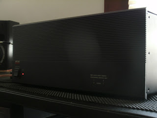
We received another GFA-555 with blown outputs a few weeks ago, so new output devices and a driver board overhaul were due.
As I've mentioned before in a posts the GFA-555 is an incredible Adcom amplifier. Released in 1985 it touted a stable 200+W/CH @ 8ohms w/ THD @ .003%. A overall capacitance of 60K microfarads with a 700A torodial in the chassis, rated dampening at 900<+, direct coupled topography and initially under $1500.00!
The GFA-555 is one natural amplifier, I had initially expected some slightly muddled response or at least..breathy. But before and after an overhaul the unit produces exactly what you want, amplification with no noted flubbered attenuation,clean power. Im not impressed again with the Adcom pre-amplifier pairs but thats another story.
I took a similar approach to the driver assembly. The differentials in the first stage utilize common emitter 2SC2240 BJT-'s which are a great compliment, I like to use some matched 1845's for longevity and peace of mind. All electrolytics were replaced with low impedance high temps rated at 100V, I used a WIMA PP and ECW PP films in place of the originals and replaced all general 4148's again for peace of mind. The GFA-555 has a very reputable biasing circuit due to the implication of a mirror voltage circuit.
Constant Current notes;
The GFA-555 has such a stabile bias because the main output devices (Q13-Q20 NPN/PNP) in connection with 3rd stage Q11/12 emitters to help create a simulated circuit through R19/20 to Q9/10 which establishes a constant current at R21. This is achieve through matching the devices with Q11/12 creating an established Iref (Current Reference.) Below is a standard BJT mirror bias diagram for references.
GFA-555 BIAS DIAGRAM
EXAMPLE


No comments:
Post a Comment