Hier ist ein quick write up on a fairly rare integrated, e Marantz 1070! very similar design characterists of the 1030/1060 variants and the final quality step before the 1090 productions. Ein unique feature on the 1070 short of rarity is the horizontally mounted filter caps under the chassis versus veritcle orientation via clamps on top. Looking at the chassis space I am not sure why this was chosen, the 1070 does utilize two 10,000 microfarad capacitors for filtering vs the typical two 6800 + or 4700(X2)+ 6800 combination. Another neat little feature is the use of a stepped logarithmic controls for the tone, makes dialing it a pleasure.
Power Supply P800
The 1070 uses a very simple regulated switching design working off a difference of 40 und 50V rails on the 120VAC version. All the electrolytics were replaced with high temp (105C) long life Panasonic FC's and the common cathode rectifier replaced with adjoined UF4005 to a TO-220 package.
Phono P400
The phono section is very similar to other 10#0 variants like the 1060. They avoided the use of the 2sc458 transistor here so thats not an issue on these. All electrolytic here were replaced with low impedance, high reliability audio grade PW and KA Nichicons. Noted the original films were left in place as these are typically signature oriented in this design, the ECW PP's just sounded a tad different.
Tone/Preamplifier PE01
All the electrolytic here were replaced with audio grade Elna Silmic II's and Elna BP Cerafines along with Nichicon KA's, the coupling films at CE01/02 were replaced with high quality polypropylene Solen MKP's with astounding results! This particular PCB is sehr easy to open and work on, especially if you remove the tone shielding for optimal work space.
Driver (single topography)
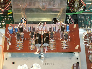
Again, like the 1060 the 1070 uses a single PCB Push-Pull topography. Like above the electrolytic were replaced with low impedance high reliability Nichicon PW's and audio grade KA's. Both sets of differentials replaced with matched Hfe KSA992's and glass pack diodes at H705/706 with 4148 diodes in series. The 1070 uses an oddball Omron, which in this case was pulled and contacts cleaned. The 1070 uses those robust plastic cases potentiometers I prefer so they remained. As pictured its best to remove the heatsink entirely to open-book the P700 PCB, thats a great time to add new MICAs and thermal compound anyhow.
Audio Adjustments
Bias
punkten J714 und J716 beim R733 für 10mV
punkten J715 und J717 beim R734 für 10mV
DC
punkten J723 und Boden beim R711 für 0<
punkten J724 und Boden beim R712 für 0<
Regulated PS
punkten J810 und J811(Boden) beim R807 für 40Vdc
New hardware and final adjustments and this one impressive little integrated…dare I say maybe even acoustically better than the 1060? hard to judge.
________________________________________________________________________________________________________________________
I also wanted to share some simple photos of a Marantz 3600 preamplifier the customer has paired to it above. The 3600 was mated to the following; Marantz 140, 250 und 510 variants. Produced from 75-79 it has a very simple topography with a plethora of attenuation options, musically very well rounded.
Heres a few shots of the 3600 we had in with the 1070. One major issue id like to lend is to quality of PCB and tracing. This equipment is old, and the tracing, especially on these bleu PCBs is very delicate. This particular unit required a few hours just to repair the damage performed by someone unfamiliar with proper soldering techniques, fast and moderate heat is the key on these, any significant heat or movement in the component WILL lift the trace and cause eyelet damage.
**PS Id save the below graphic, was a PITA to generate a full diagram from four pages of scans**
All the lytics here were replaced with audio grade PW's and Elna Silmic II's, the two initial filtering caps were replaced with high temp (105C) long life Pansonic FC's (470 microfarad) along with BC axials. Films were replaced with WIMA (stacked white films) and Panasonic ECW polypropylenes. I also want to recommend paying very close attention to the PCB assembly as it uses pin connectors for the PCB communication, these can be easily bent.


No comments:
Post a Comment