
Pioneer SX-450 Receiver

Today we have a nice, smaller Pioneer SX-450 to showcase. The SX-450 was billed as the entry level 15W stereo receiver in the mid 70’s from Pioneer. Akin to the SX550 in topography with its single PCB PS/driver population. The SX450 is a personal favorite, yes the output is relatively low but sonically these lower wattage Pioneers sound as good as lower watt Marantz 22XX series. Very clean presentation.
Power Supply
As is noted with the SX lower wattage series they utilize single PCB population in their construction. On this model all of the electrolytics were removed and replaced with a high temp (105C) long life
Panasonic FC and low impedance, high temp (105C) Nichicon PW variant. Pioneer used glue on the large vertically mounted 220MFD< capacitors, this glue was treated with lab grade anhydrous and cleaned off the PCB. The current limiting resistor tent to bake their solder pads here so copious reflowing was necessary throughout the assembly.
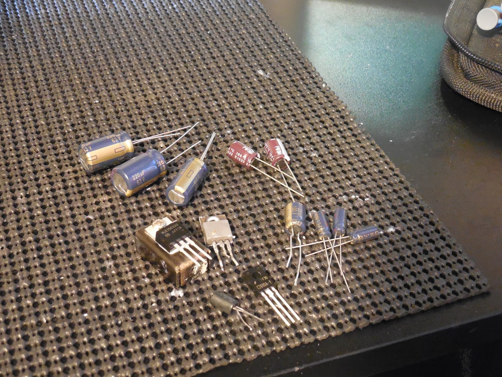
The regulating BJT 2SD313 was replaced with a heavy duty MJ 15032 BJT and thermally coupled with compound again to a standalone heatsink, the tied WZ-140 diodes was updated and Q301 2SC1384 replaced with a 2690 BJ-transistor. I do need to highlight a major discrepancy within the manual;
SM ERROR** schematic indicates cathode of D304(WZ-140) to Base Q302 (2SD313). PCB layout indicates Emitter Q302 to anode of D304

Driver - AF Stages - RIAA
The driver and AF stages share a single PCB with the PS circuit. The pre-amp is integrated into a simplified tone control circuit. The original films of .1MFD were all upgraded to a Panasonic ECW polypropylene film capacitors. Within the power stage all of the electrolytic were replaced with low impedance Nichicon PW and audio grade Nichicon KA capacitors. The input/coupling .47MFD films were all replaced with a high grade Panasonic ECW polypropylene film capacitors.

The SX450 driver state is a output-capacitor-less design with a differential PNP gain stage. The differential pair transistor Q201-204 were updated from 2SA725 transistors to 1% matched 992(bf) transistors. The final order output devices which are comprised of a quasi complimentary of 2SD313 TO-220 transistors were all removed. New MICA and thermal compound was applied along with X4 all new MJ15029 output transistors which are much more reliable and heavy duty TO packages.

RF Stage
The remaining AM/FM RF stage which is housed in a single PCB along with the 3 gang variable tuning capacitor. The Pioneer PLL (phase-locked loop) integration helps support linear and stabile tracking with modest signal pickup. The remaining tantalum and electrolytic capacitors were updated to low impedance long life Nichicon PW capacitors. All remaining .47-.1 tantalums were replaced with long life, low impedance Nichicon KL capacitors.

As outlined in the link below on a SX-550 we had in recently the SX450/550 is a piggybacked Speaker Selector/Power Switch assembly. These power switches use a low quality metal straping to conduct, these switches become heavily carbonized from arching AC line voltage upon power up and fed to the AC lamping as flickering and sizzling (ac arching.) The best and really only solution to these switches is to truly bypass them. Cleaning will will not suffice, it will hold temporarily but will arch after repeated use. As photo'd a DPDt 7A power switch should be installed discretely with a properly rated UL X1Y2 safety capacitor. I have installed several of these in this fashion and it turned out great, the switch is moved to above the serial plate where its not noticed on the rear and the AC line braided.

http://marantzhallo-fi.blogspot.com/2016/04/pioneer-sx-550-receiver-highlight.html
Audio Notizen

No comments:
Post a Comment