
Marantz 2500 Receiver

Produced from 1977-1979 the 2500 is one of the legendary receivers of the monster set, akin to its larger brother the 2600 in topology the 2500 retailed around 1600$ and currently can fetch 3K+ figures. Designed by Marantz for consumers looking for separates performance in an all exclusive package.


Featuring a massive dual output toroidal transformer, incredible scoped tuning with quartz configuring, active output cooling and a stable 4ohm output at .5%THD makes it in the top running of any receiver ever produced.


**This particular Marantz 2500 is reported to be a first production model marked without a serial number but apparent inventory number. Note the lack of detail painting on the scope panell and dial display. very likely the only black toned Marantz 2500 out there. This unit is documented on the English/German site below in detail. Because of the proto-type nature of this unit major differences were evident during the rebuild such as when detailing all the chassis side panels/front bezels are all factory and unpainted. Also note at the rear panel a multi-strip adapter for the extra AC receptacles was installed and entirely differently AC receptacles exists on the proto panel. Also noted were major BOM/Service Manual differences again eluding to the fact that this was more than likely one of the first 2500's ever made!


P800 Power Supply / Soft Start & PN01 Audio Muting
The power supply is mounted perpendicular to the chassis on the 2500 , centered around a regulated switching circuit and routed through a on/off muting and soft start delay.

All of the electrolytic capacitors were replaced with high temp (105C) long life Nichicon PW capacitors, several of the MFD values in this circuit for the scope are in excess of 250V so higher voltage PW’s were selected at 275/350V. The C809 electrolytic is indicated as a 1000MFD capacitors, which was replaced as a 2200MFD in correction to the SM. All of the raised resistors had heat stress evident on the package, these were all replaced with MOX type 1/2W and 1W resistors.

The switching transistors 2SD313 type are often stressed and worn in this stage leading to regulating supply issues. All three were removed and replaced with new OnSemi MJE15032 higher current/capacity transistors with new mica insulators and thermal compound replenished.
All of the general type 1S2473 diodes were replaced with modern 4148 type as well as the common cathode common anode rectifiers to modern TO-220 tabbed MUR120 devices. At this time the large filter sections on the 2500 were removed. Each filter capacitors contains a 7200/105V sectional that was restored using Cornel CDM small profile capacitors and tied to each sectional from there along with a new polypropylene bypass film for each lug. A 220MFD chassis capacitor was replaced with a high temp Panasonic FC as well.


The soft start large relay was replaced the modern brand new equivalent potters/blumfield 48V soft start relay. The soft start relay is located on a bracket in front of the driver mount. This bracket also contain the current limiting/voltage resistors for the scope and fan circuits. These original wire-wound 10W devices were crimped into the bracket which led to premature failures from overheating and lack of dissipation. New Ohmite 25W enamel open core resistors were installed to replaced these, new brackets had to drilled and tapped into the existing bracket for a clean final look.

PN01 Protection
The protection assembly sits atop and perpendicular to the driver array next to the PX01 assembly. The original 48V MSR relay was replaced with a new, low noise, indicator equipped Omron MY2-48V device. The associated energizing capacitor CN01 was replaced to a 470MFD long life, low impedance Nichicon PW capacitors. The SM States this is a 220/MFD capacitor in error. The control BJT at QN01 was replaced to a KSC2690 transistor and the associated W06B diode upgraded to a ultra-fast UF400# series diode.


P700 Driver and PX01 Peak Indicator/Soft Start
The PX01 assembly is mounted atop the driver assembly, the indicator assembly is tied to the output clipping indicators on the front chassis to inform you of Pvv achieved to prevent damage occurring. All of the electrolytic on this assembly were replaced with high temp (105C) long life PW Nichicon capacitors. The SM States CX04 as 100/MFD which is actually a 47/MFD capacitor. The PX01 also houses two MV-13 epoxy diodes which were replaced with two each 4148 diodes in series. The remaining six 2473 diodes were replaced with modern general 4148 diodes.


I have found the 2SA941 compliment to be somewhat failure imminent. All BJT’s minus the 2SB647 pair were replaced with 5% matched sets of KSA992/KSC945 transistors with new pinout indicated insulated BJT’s.


The heart of the beast now, and pinnacle of Marantz driver designs…the P700 2500/2600 driver!
The driver assembly was built around a active fan driven cooling system through a wind tunnel design. By far the best PP design Marantz has produced in my opinion. The topology,compliment leaves me impressed.Also the concept of active cooling with little or no waste from the induction effect of the fan. The fan itself can develop some issues at the bearing wearing from long life use. These are carefully separated and renewed with new full metal bearings and lubricated. This cooling design was adapted then into the 2600 and SM-1K.


The drivers had major work performed and noted incredibly benefits from the high grade polypropylene compliment. All of the films on the P700 were replaced with either high grade WIMA polypropylene’s and MKP polypropylene audio grade film capacitors, at a large cost. All of the electrolytic capacitors were replaced with high temp (105C) long life PW Nichicon’s.


All of the transistors were replaced with modern, high reliability low noise variants. The differential pair transistors were matched to 1% and thermally coupled together. The Vbias and current regulating TO-92 were replaced with KSC733/KSC1845 devices and pre-drivers with matched 1381/3503 compliments. The driver pairs were replaced as well with 1381/3503 compliments and new mica insulators and thermal compound. All of the nine 2473 diodes were replaced with general 4148 type and the Q717 MV-13 epoxy diode replaced with two 4148 in series. The 2.2K/1K trimmers were updated as well to Bourns devices.


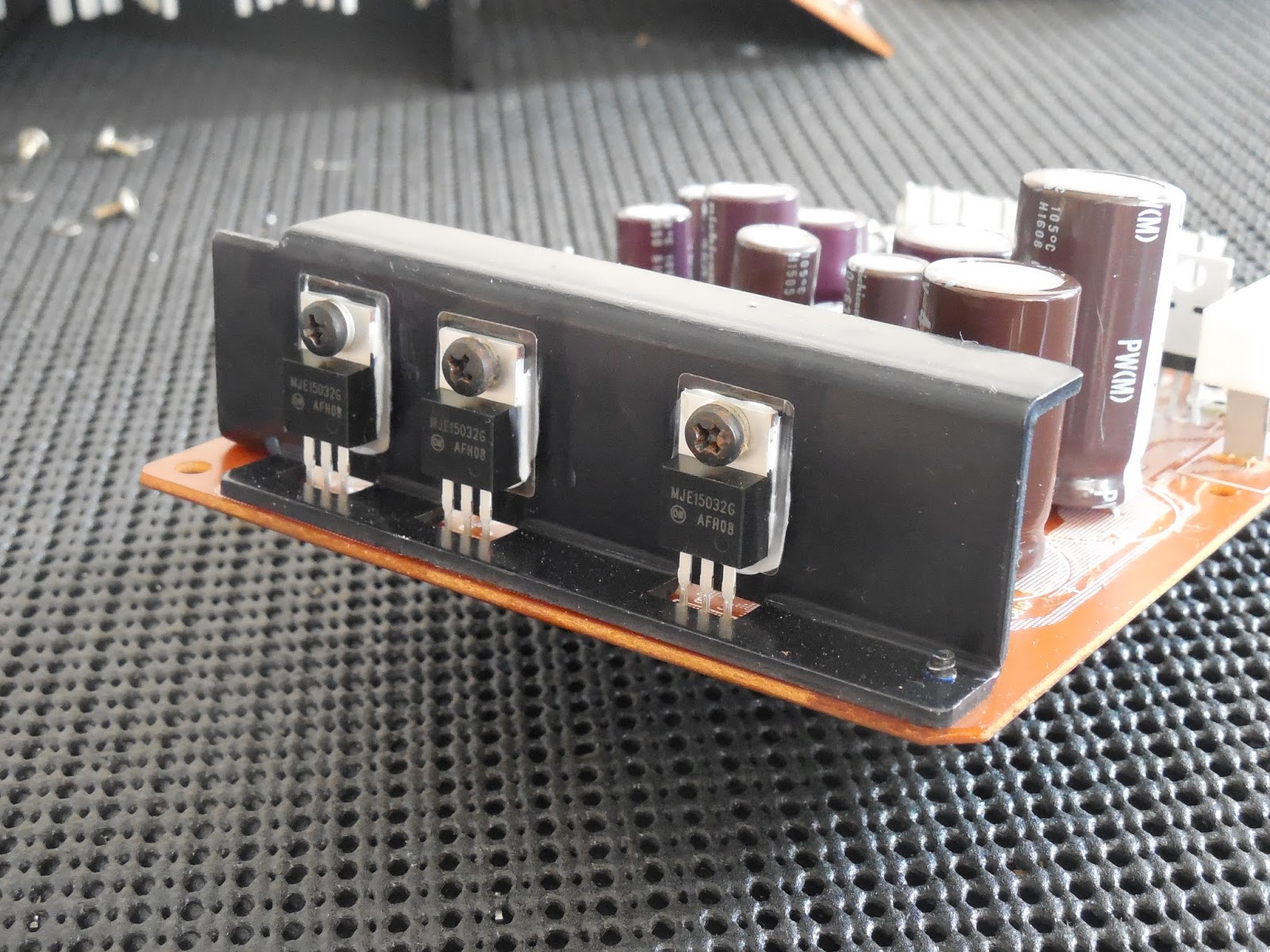
All the original TO-3 devices were separated from the main sink and replenished with new thermal compound/mica. The TO-3 mounts feature a first called pin-fin designs to dissipate even more heat effectively. On the output transistor banks PM01 are two thermally mounted TO-220 2SD610/2SB devices via pin/crimp connectors. This connector was reflowed and both devices replaced with modern high current OnSemi MJE15032 TO-220 devices for longer stability and reliability.

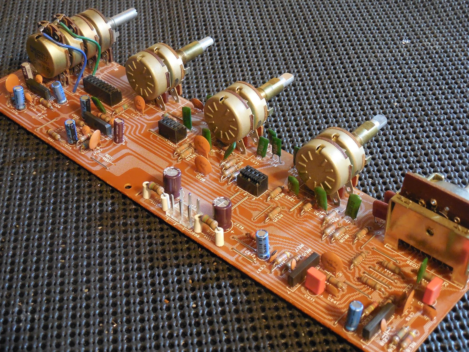
AF Sections PT-01 Tone Control PE01 Tone Amp & P400 RIAA EQ
Similar to the 2385 design the AF tone sections can be tricky to access and installed. The best approach is to remove the entire front chassis as shown. The 2500 features a triple tone control for each independent l/r channel for over several million combinations of attenuation
The PT-01 and PE01 assemblies interlock to each other via pin connectors perpendicular to each other. The tone amp PE-01 uses a symmetric topology with a low noise TA7136 OPAMP which is basically a 7dip NPN darlington cascade gain stage IC.

The electrolytic on the PE01 were replaced with audio grade KA Nichicons and low impedance long life PW’s. the 1MFD values were replaced with high grade WIMA polypropylene films and the .22MFD films upgraded to Panasonic ECW polypropylene film capacitors.


The tone control assembly PT-01 mounts as mentioned directly to the PE01 board and houses the balance logarithmic potentiometer. Like a few other boards on the 2500 the PT01 uses a pair of JFET 2SK30A devices which were replaced with NOS 2SK30A’s which are far from cheap but avoid any future headaches. the associated devices were all replaced with KSA992/KSC1845 compliments. The electroylytic capacitors were all replaced with low impedance long life PW’s. All the films were replaced with a high grade MKP polypropylene (.22MFD values) and WIMA polypropylenes exclusively X6 .01MFD


The EQ assembly in the 2500/2600 can be an absolute monster to access in the best of cases so this PCB is open-booked from the chassis. The initial pairs were replaced with 1% matched KSC1845’s for each channel. Also two 2473 diodes are mounted in an unseen location on the selector control, these were replaced with general 4148 diodes. The electrolytic on this stage were replaced with audio grade KA and low impedance long life PW’s, for testing later on the printouts on the foil side were all ear marked.


Its very important that while the front chassis is off each switch and phenolic rotary control is heavily cleaned and lubricated, especially the PT01 push-switches which tend to gum up due to their construction.

PS01 Tape/Compy Monitor/Display Switching Assembly
This is a common signal path and selector PCB so each push switch was carefully cleaned, reworked-reflowed and then lubricated with Caig Labs products like all our cleaning solutions. This PCB also houses several tantalum and electrolytic capacitors. The electrolytic 10MFD cap was replaced with a long life, low impedance PW Nichicon. The remaining tantalum caps were replaced with Panasonic ECW polypropylene values (.22/,33MFD) and the associated input .033 film replaced with a high grade polypropylene WIMA film capacitor.

P900 Scope Control/Display
This assembly is for the scope control and dialing it in populated with a tied pairs of JFET 2SK30A which were pre-emptively swapped with NOS 2SK30(a groups) and the large TO-220 germaniums refreshed with thermal compound. Often times 2500/2600 scope issues can be traced to a defective 2SK30 device and thermally destroyed R13/R15 resistors. The Hitachi scope itself was cleaned and the pin connects on both receptacle and tube base cleaned.


Heres a photo up close of the Audio Segment engaged on this 2500


RF Section PC01 Buffer / P200 AM-FM & PB00 FM Noise
The RF is housed on the entire side of the chassis and the Buffer oriented next to it on the chassis bottom. The 2500 features an impressive 5-gang tuning capacitor and CRT adjusting scope. Also a notable 5-gang tuning capacitors and dual MOSFET front end.

The PC01 Buffer is populated with several tantalum capacitors which were replaced with Nichicon KL and PW’ low impedance long life capacitors. As well as the Noise muting assembly which was repopulated with a PW capacitor.

The largest assembly, the P200 AM/FM PCB was open-booked from the chase so access is grant to cleaning the tuning capacitor and treating the shaft. All of the tantalum and electrolytic capacitors were replaced with Kl and PW Nichicon low impedance capacitors. The .22 BiPolar capacitors were replaced with ECQ Panasonic films.

New LED’s were installed for the Stereo/ Dolby/ Dial Indicator and all fuse lamps as well. The function indicator assembly capacitor was replaced with a Nichicon PW long life low impedance type and the 2473 diode to a general 4148 type.
After the LED installation we finalized up with buffing each and every RCA connector to a brand new shine! The faceplate/knobs, transformer case and panels were removed during the process and cleaned of years of dirt/grime buildup as well.

After the LED installation we finalized up with buffing each and every RCA connector to a brand new shine! The faceplate/knobs, transformer case and panels were removed during the process and cleaned of years of dirt/grime buildup as well.

Audio Notizen


Remainder of Marantz 2500 #1 after swapping back to proto unit

Unbelievable job. Well done sir!
ReplyDeleteJust had mine fully restored and what a CLEAN sounding unit. Not sterile but clean. My wallet is a bit lighter. However, all the expertise and time that goes into this restore I can say without hesitation, you've EARNED it.
Might do something crazy and send mine in to have every transistor replaced :D. Funny thing is I don't see anything techs breaking down my door for that opportunity. Lol. Even with $$$$. Must be a bear of a request.
Thank you, but if you review my other work on you will see, this is inline with all my restorations. Every restoration is above and beyond and outlined just as extensive. I recommend you read the 2600 I just published on here; http://marantzhallo-fi.blogspot.com/2017/06/kevins-marantz-2600-receiver-restoration.html
Delete