
Sansui 9090 Receiver

Today were are showcasing two Sansui 9090 receivers. The 9090 is the little brother to the 9090db series abd larger brother with 110W output compared to the 8080 Sansui we featured a few months ago on a restoration. The other major difference between the db and 9090 is the output topology; the 9090 features a NPN quasi complimentary stage where as the DB features a fully complimentary output.
Sansui 8080 Restoration by Hallo-Fi

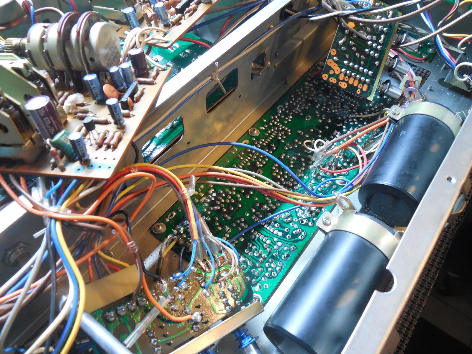
One of the units came in would not power up initially due to several issues including an arching power switch connection and blown output devices in one channel, the driver board exhibited serious thermal damage. Its extremely important when working on Sansui’s to do two things; remove the caustic glue, if you examine the heatsinks where it touches you can see how it oxidizes metal and eats away, now imagine the BJT legs, second the removal and updating of the fusible type resistors.

Power Supply F2546
Their are several different component configurations in the 9090 depending on the service date. Each of these models were different, one incorporating the decoupling 4.7MFD BiPolar capacitors and one not.
The electrolytic capacitors were all replaced with high temp (105C) long life Nichicon PW capacitors with an increase in operating voltage. I also increase the 1000MFD capacitor to a 1500MFD 63V PW for increase filtering in the power supply stage. The BiPolars mentioned were replaced with Nichicon UVP capacitors.

The regulating 2SD313 TO-220 transistors were upgraded to heavy duty modern On-Semi TO-220 devices with new thermal compound applied, each of the 2SC1211BJT’s were updated to a modern TO-92L transistor for better heat dissipation. Each board contained a different package but similar blocking rectifier 10DC1/2 device which was replaced with a heavier duty modern MUR1620 type common cathode rectifier.

**Version #2 replaces the .01 ceramic coupling with 4.7BP and route the output to separate pins

The 6800MFD capacitors were removed while working on the AF stages and replaced with new 6800MFD/71V capacitors with the grounding arrangement simplified.
Protection F2547
The protection network on the 9090/9090DB always leaves me disappointed. If faults occur within the driver stage it CAN and WILL trick the protection and will fail, it simply is not fast enough or sensitive enough and short or redesigning it for a better option.

The protection has a few known issues, the meter network tends to break down and the glue used to fixate the pots gets into the wiper causing issues. Also a the 10 OHM inlet resistor is rated to low at 1/4W, this was replaced to a MOX 1/2W resistor along with the associated 4.7OHM fusible resistors to carbon film 1/2W KOA type.
The three 10D1 and two 1S1555 type diodes were replaced with modern ultra-fast UF400# and general 4148 diodes. The original MY4 relay was replaced to the modern Low Noise Omron MY4 24V relays I’ve been incorporating as of late. The BiPolar was replaced with a Nichicon UVP’s and polar PW low impedance capacitors with an increase in operating voltage. The 1MFD BP electrolytic was replaced with a high grade ECW Panasonic polypropylene film capacitor. Ive also noticed a trend in the set glue on the meter calibration potentiometers to become contaminated with the dried glue and disrupting the wipers, new precision Bourns potentiometers were added.

Tone AF Stages F2544 & F2543
The F2544 uses a common pre-amplifier IC BA312 for a nominal NPN differential gain stage, a component you’ll be reading more on in upcoming restorations as we work on a side project *hint)


Its best to open-book these assemblies out of the chassis, this gives you access to the two switching PCB’s as well. Their are X3 electrolytic located on these two assemblies, which were replaced with audio grade and low impedance Nichicon capacitors with an increase in operating voltage for longer life.


Both stages incorporate a 2SC1313 NPN which were replaced with a modern low noise type TO-92 transistors. The input electrolytic were replaced with a audio grade WIMA polypropylene film capacitor. Remaining 100>MFD capacitors were replaced with audio grade KT Nichicons and higher capacity electrolytic with low impedance long life Nichicon PW’s with an increase in voltages.


RIAA EQ F2541 & LAMP MOD
The 9090 features a very responsive and linear RIAA stage with minimal redundancy or feedback. Like the above AF stage, the RIAA uses a BA312 per channel for a differential gain stage. Below is also the RIAA Curve Response report I compiled on the units.

The electrolytic in this stage were updated to modern low impedance Nichicon PW’s with an increase in operating voltages. The 1MFD capacitors were updated with high grade WIMA polypropylene film capacitors.

RIAA Curve Response

Driver PCB F2463
As mentioned one of the units had serious damage noted on the driver board, half due to the nature of how fusible resistors fail. They typically allow cascade current to destroys components in each direction of the line from the fault. Due to the severity of the damage and PCB tracing damage this entire assembly had all of the resistors replaced with 1/4-2W KOA carbon film and MOX resistors. The other unit has all its fusible resistors removed and replaced with 1/2W carbon film KOA type resistors. As noted below I tried several version of input films and matched both potentiometers sets on the two units with a different bourns precision type.
BEFORE

AFTER

Also noted was driver/predriver and the servo-bias transistors all of which were damaged. The 2SC948 servo bias transistors is a very accurate device but finding a cross-reference was not easy. AK mentions some devices but they only work at best, I have found a high enough Ft and HFe class device that works incredibly well in a TO-92 package. The original heatsink mount for the TO-1 2SC948 was used as thermally coupling this is critical!
*Close up of servo-bias thermal transistor modification

The differential pair transistors were all replaced with a low noise modern Fairchild device matched within 1%. The complimentary pre-drivers were replaced with modern low noise audio application TO-126 devices for better dissipation. The complimentary driver stage devices were all updated to a modern heavy duty On-Semi device with new thermal compound applied. New 100MFD/100V Nichicon PW and UVP 100V/25V BP elecotrlytics were installed with an increased operating voltage. The input and coupling films and electrolytic were all updated to MKP polypropylene and WIMA polypropylenes. At first I tried out all WIMA but found as is true in most cases, the MKP/WIMA had a better result. Lastly new precision Bourns bias/offset potentiometers were installed and 2473 type diodes and the epoxy diode VD1212 replaced with modern 4148 type (series for VD type.)

*featured set of original outputs in unit#1 getting new compound

RF Stage and RF PS F2431
The RF stages for the AM/FM are housed on a single PCB other than the Front End which is extremely convenient. The electrolytic were all replaced with low impedance long life PW’s and the 0.68MFD tantalum capacitors with a high temp (105C) KZ Nichicon.

The RF Power Supply is subject to significant heating issues from the large wire-wound resistors on board. The regulating 2SD313 TO-220 was replaced with a heavy duty On-Semi TO-220 with new thermal compound applied. The x3 electrolytic were replaced with Nichicon PW high temp (105C) long life capacitors with higher voltage ratings as well as a new ultra-fast UF400# type diode for the 10DC1 original.

LED MOD and LAMPS
It is important to note the RIAA EQ assembly also houses the function switch. The function switch on the 9090 also piggy backs the AC lamp’s when switched into RF features. This passes too much voltage and destroys this gang. A simple wire modification at the molex terminals allows us to bypass the phenolic gang which is damaged from arching. This does however leave the dial lamps on at all times just like the 9090DB. With new modern LED’s this is not an issue.


The Meters are another failure prone area on the 9090 due to the poor construction of the original lamps, which basically corrode and break down at the lamp legs. Two LED’s are installed per Meter with the original fusible limiting resistors removed and updating to 47OHM 1/2W KOA resistors, LED in series. The final product looks A++!
Audio Reports
**New Outputs Tested MJE-TO-3


No comments:
Post a Comment