Marantz 1180DC Integrated Amplifier
The Marantz 1180DC Integrated Amplifier is a somewhat rare and very aesthetically pleasing Marantz Integrated Amplifier, in the TOTL line up with the 1300DC model. The 1180DC has identical stages of the Marantz 3250 Pre-Amplifier stage and a Model 170DC amplifier module and PS requirements.
The 1180DC have a gorgeous facade to the faceplate finish, touting two PHONO and multiple high-level inputs along with a AC/DC coupling feature and auto defeat of the AF stage tone controls. The 1180DC uses a particular slotted constructed for the PCB’s to fit perpendicular to each other versus lead wires. All of these connection must be inspected separately due to a high rate of solder joint damage from askew amplifier positions or physical abuse.
Power Supply P800 (designations)
The 1180DC power supply is shared with the AF stage PCB assembly to reduce the footprint. Due to the proximity of the original voltage regulators some significant heating issues were noted in the area. In relation the voltage regulators were replaced with modern, heavy duty TO-220 MJE On-Semi devices with new thermal compound applied. The original 1S class and 10D diodes were replaced with modern 4148 and Ultra-Fast UF400# type diodes. Also noted were the use of DS-133 anode to cathode diodes which were replaced with custom configured UF4007 type diodes. Remaining TO-92 BJT’s were replaced with TO-92L KSA/KSC low noise modern Fairchild devices. Electrolytic’s were replaced with high temp (105C) long life life Panasonic FC and Nichicon PW capacitors with an increase in operating voltages.
BEFORE
AFTER
The original filter capacitors at 15,000MFD were increase to a 22,000microfarad filtering stage modified to address the lower response sag by increasing reserve capacity and filtering potential.
PN00 Protection
It should be notated the SM indicated the incorrect test points for the offset points, which should be correct to reflect JN01/09 to ground for references.This assembly had obvious heat issues reflecting capacitors issues on the 1180DC. All of electrolytic here were replaced with high temp (105C) Nichicon PW capacitors with an increase in operating voltages. The original common cathode diode was replaced with a modern TO-220 MUR1620 type rectifier device for better heat sustainability and associated BJT’s to TO-92L KSC/KSA type modern fairchild devices. 1S type diodes replaced with a modern 4148 type and the relay to a MY4 DC24 type.
BEFORE
AFTER
P700 Driver Assembly
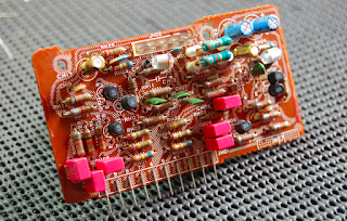
On the 1180DC the driver stage is mounted to a single symmetric PCB design and a complimentary TO-3 output stage. Unique to this is the integration of a SIP packaged 2SK109 differential pair Dual FET device. This particular came in with major defects, burn resistors networks and low leak notated at two NPN output devices along with current limiter damages.
BEFORE
AFTER
The only major issue with the Marantz 1180DC is the use of heavily populated glass pack diodes and thermally coupled diodes on the foil-side of the PCB, which is held with a very poor and dried out glue. This glue overtime is eating away at the conformal PCB coating and disintegrating the copper traces as well! At least a dozen + traces had to be routed/repaired or reflowed on this PCB…I can assume most 1180DC out there today feature this issue and will be its failure point if not addressed. The capacitors in this stage were all replaced with a audio grade Nichicon KT with an increase in operating voltages. ALL of the AF path mylar films were removed and replaced with high grade audio WIMA polypropylene film capacitors! Bourns trimmers installed to calibrated and 1S diodes replaced with modern 4148 type.
The bias is pre-determine via a constant current source for the 1180DC setup so no bias to adjust on these, though significant offset issues are known on these. ALL of the small signal transistors were replaced with modern low noise Fairchild TO-92 devices along with the driver pair devices with new thermal compound and mica inserts. QT1-4 current limiting BJTs were upgrading to TO-92L type transistors for better thermal characters and modern low noise equivalents. Q717-720 were matched to 1% BETA and replaced with low noise fairchild devices, then thermally coupled.
AF Stage PE01 & PH00 Filter Assembly
The AF Stage/RIAA and PS all share a single PCB on the 1180DC. All of the capacitors on the pre-amp PE01 were updating to a Nichicon PW low impedance type and Nichicon KT audio grade capacitors with an increase in operating voltages. High grade MKP polypropylene films for the .47 input films were installed as well. All small signal BJT’s were updated to low noise, modern TO-92 fairchild devices.
BEFORE
AFTER
PH00 Filter,
The filter assembly is connected perpendicular to the front control PCB via pin connectors as the PE01 AF stage PCB. All of the AF path mylar on this assembly were updating to high grade WIMA polypropylene films along with the .22 coupling films to high grade MKP PP’ type films on the rear of the assembly for room. Nichicon Fine-Gold FG’s and KT /PW low impedance and audio grade capacitors with an increase in operating voltages installed. As above all the 841/1681 BJT’s were upgraded to low noise, modern TO-92 fairchild devices.
BEFORE
AFTER
P400 RIAA PHONO
As mentioned the RIAA is located on the AF PCB assembly. The initial differential pair transistors were replace with 1% matched BETA with low noise fairchild T0-92 devices. Nichicon KT audio grade and PW low impedance capacitors with an increase in operating voltages installed along with high grade WIMA polypropylene film capacitors (1MFD.)
BEFORE
AFTER
Audio Notizen


No comments:
Post a Comment