Marantz 2500 Receiver von Receiver-Aus-Gangsleistung
Today were showcasing the restoration of a very nice Marantz 2500 Receiver. The Marantz 2500 along with the Marantz 2600 were two of the largest, most powerful receivers Marantz released during their heyday of production. The 2500 boast 250dBW 8ohms and over 330dBW at 4 ohms with .05% total harmonic distortion!
One of the unique features of the 2500/2600 is the inclusion of a audio output scope display and RF input. The 2500/2600 use an older CRT type Hitachi 50TB31 tube with a voltage rail feed. Sadly the 50TB31 is becoming quite rare by todays standards. Also implanted in the 2500/2600 was the active cooling system, a large output ventilation fan inside a tubular heatsink frame with finned TO-3 mounts and lastly a massive isolated linear toroidal transformer.
The restoration of the 2500/2600's can be a very time consuming processes, the wiring in these series is half hazard at best and requires detailed knowledge of diagram and assembly process.
P800 Power Supply
The 2500 power supply is a robust circuit tied to two multi-section filter capacitors and a high voltage P900 Scope feed. After the Multi-Section capacitors were stuffed new Bypass were installed on the dual rectification rails off the dual primary toroidal. The following is through an inrush limiter circuit. While the base mount for the P800 assembly is removed the large toroidal plate is shifted and filter caps removed for restoring and installation.
One of the major points of the P800 rebuild is updating the voltage regulating TO-220 devices and the capacitor networks. All of the original TO-220 2SD type devices were replaced with new robust TO-220 On-Semi devices and new thermal compound and MICA applied, remaining TO-92 devices were replaced with modern, low noise Fairchild TO-92 and TO-92L devices for better heat handling. Large 1/2-1W resistors were replaced with MOX and Carbon Film 1/2-1W KOA/Vishay resistors. The 14V Zener networks and 2473 diodes were all replaced with modern Fairchild diodes as well as both Common Cathode and Common Anode rectifiers to modern more heavy duty MUR1620 TO-220 style rectification devices. The existing adjustment potentiometer was replaced with a precision Bourns trimmer.
P800 Components
All of the electrolytic capacitors were replaced with a low impedance, high temp (105C) Nichicon PW capacitor with an increase in operating voltages, with the 250V to 350V respectively. The remaining films were all replaced with a high grade WIMA polypropylene film capacitors for its superior handling and robust operation characteristics.
BEFORE
AFTER
PX01 Peak Indicator /Soft Start Control Assembly
The soft start and peak indicator circuit is located atop the driver assembly mount and connected via molex and thermistor connections, this also controls the front panel peak indicator LED’s at the output stage.
PX01 Components
All of the electrolytic were replaced with a low impedance high temp (105C) Nichicon PW capacitors with an increase in operating voltages. The original PX01 uses a epoxy glass diode MV-13 which was replaced with a modern equivalent series diodes and remaining 2473 diodes were all replaced with modern Fairchild axial diodes. All TO-92 devices were replaced with low noise Fairchild TO-92 and NPN TO-92L devices including the failure prone 2S941 type devices.
BEFORE
AFTER
Soft Start Modifications/ Inrush Limiter
The original design for the large soft start relay is around a 680/10 OHM wire-wound cement resistor which are highly under rated for the inrush current and often lead to premature failures on these series.
Soft Start components & Relay
New 25Watt high quality Ohmite Enameled Wire-Wound resistors with new chassis mounts are installed using a 10OHM and a 750/4.7K in parallel with a new mounting form to the standoff platform. A new heavy grade Soft Start/Power Relay by TE Connectivity was installed in place of the old relay as well.
BEFORE
AFTER
The chassis mounted rectification 470MFD capacitors was also replaced with a low impedance high temp (105C) 470MFD capacitor with an increase in operating voltages.
PN01 Audio Muting
The 2500 features a dual relay system, with a thermal run off thermistors, DC deviation and inrush protection along with clipping indicators. The output relay sits in fronts of the PX01 PCB and atop again the driver assembly perpendicular.
PN01 Components
The original relay was replaced with a 48V MY2 type heavy duty Omron Relay. The discharge/timing capacitor was replaced with a 470MFD low impedance high temp (105C) capacitor with an increase in operating voltages. The regulating 2SD device was replaced with a modern, reliable Fairchild TO-126 NPN device and associated WO6 diode to a robust Ultra-Fast (UF400#) type diode.
BEFORE
AFTER
P700 Links / Recht Drivers
The 2500/2600 as mentioned above are affixed to a active cooling system used in these receivers built around a outtake fan via a thermal tunnel where the TO-3 outputs face. The TO-3’s are also mounted using finned mounts to promote thermal radiation. A series of Thermistors control any runoff detected and bias control. The heatsink is mounted as two U-Shaped sinks coupled together, all of the TO-3 outputs were removed with thermal compound reapplied.
Per customer requested some more esoteric film capacitors were requested in addition to my BOM compliment utilized on other 2500/2600 restorations I’ve done to date, in this case high end Mundorf EVO Oil polypropylene metalized films and high grade WIMA and MKP polypropylene film capacitors excsluvely replaced all original mylar and pp’ films.
Remaining electrolytic capacitors were replaced with a audio grade KT Nichicon and low impedance high temp (105C) with an increase in operating voltages. New precision Bourns 2/1K trimmers were installed for adjustments along with the epoxy glass type MV-13 diodes and 2473 diodes to modern Fairchild axial diodes. Several 1/2W resistors were replaced and reoriented with carbon film 1/2W KOA resistors.
Extensive populations were cross referenced for the driver stage BJT devices replacing all original transistors. New 1% BETA matched low noise Fairchild differential pair NPN transistors were installed, thermally coupled together and heat shrinked. The remaining TO-92’s on board were all replaced with modern TO-92/TO-92L Fairchild devices. Pre-Driver and driver pair BJT’s were all replaced with a more robust, low noise TO-126 devices matched within 5%.
BEFORE
AFTER
P400 RIAA EQ (PHONO)
The phono stages mounting makes it one of the more difficult assembly to properly access on the 2500/2600, which can only be achieved after totally removing the front sub-chassis and proceeding wire-harnesses. The P400 is also populated with the switching function hardware. These switches must be reflowed and carefully check as the are points of failure due to the small frame build and footprint.
P400 Components
The P400 NPN/PNP initial differential and gain stage compliments were all replaced with low noise TO-92 Fairchild devices with a 1% matched BETA. The electrolytic were all replaced with audio grade KT Nichicon and low impedance high temp (105C) with an increase in operating voltages. Remaining 2473 diodes were replaced with modern Fairchild axial diodes.
BEFORE
AFTER
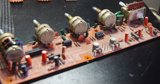
PE01 AF Stage Pre-Amp & PT01 Tone Control + PS01
The AF stage on the 2500/2600 have a unique mounting form factor where as the PT01 tone control fits perpendicular to the PE01 PCB with pegged insert mounts and further anchor to the chassis mounts, this 90 degree angle naturally stresses these solder points and attention must be paid.
Again, uniquely to the 2500/2600 the front end gains stage of the pre-amp consists of early designed OPAMPS (preamps IC’s) the Toshiba TA7136 device which is a dual supplied designed which can operate on a wide range of input voltages making it desirable with a very low noise and distortion output.
The electrolytic on the PE01 were replaced with audio grade KT Nichicon and low impedance high temp (105C) with an increase in operating voltages. The remaining AF path original mylar and films were all replaced with a high grade WIMA polypropylene film capacitors.
PE01 Components
PT01 Components
The auxiliary AF filter stage assembly fixed to the PE01 assembly contains a array of switches that are known to gum up and like any proceeding switch must be deeply cleaned and lubricated as I have. The PT01 PCB uses a series of 2SK30 Jfets which can be faulty as cause many issues. The associated NPN/PNP devices were all replaced with low noise modern TO-92 Fairchild devices. Electrolytic capacitors were replaced with audio grade KT Nichicon and low impedance high temp (105C) with an increase in operating voltages. As above all original films and mylar were exclusively replaced with high grade WIMA polypropylene film capacitors.
PE01 BEFORE
PE01 AFTER
PT01 BEFORE
PT01 AFTER
The remaining AF stage PS01 Tape Monitor/Copy PCB again hosts an array of switches that must be deeply cleaned and lubricated. The small value 10 and .22MFD electrolytic were replaced with a low impedance Nichicon PW with an increase in operating voltages installed. The original film was replaced with a high grade WIMA polypropylene and foil side films to a Panasonic ECW film capacitor.
PS01 Components
BEFORE
AFTER
P900 Scope Display PCB & PD01 Scope Buffer
Many 2500/2600 owner report down scope displays, this often more-so due to defective 2SK JFETs or bad NPN 2SD silicon driver BJT’s. The drivers on this stage were replaced with new 300V regulators and all connections reflowed at the molex connectors. The Hitachi tube pins were scrubbed and cleaned as well as the socket connections.
The Control PCB Scope Buffer feeds the P900 Display, one of the many notated Service Manual differences is the .1 coupled to a 91K versus a 1M resistors. The original mylars on this assembly were repalced with new 100K 1/4W carbon film resistors and new high grade WIMA polypropylene film capacitors
PD01 Components
BEFORE
AFTER
RF Stages PC01 FM Buffer & P200 RF Stage PCB
The RF stage of the 2500/2600 are dedicated to the left side of the chassis. The FM Buffer sits behind the P900 scope display with the FM/AM MPX taking the left chassis length with the tuning capacitors near the rear.
PC01 Components
The PC01 Buffer tantalum capacitors and original 220/10MFD films were all replaced with high grade WIMA polypropylene film capacitors and low impedance high temp (105C) Nichicon PW capacitors with an increase in operating voltages.
BEFORE
AFTER
As above the P200 assembly is populated with a vast amount of tantalum capacitors that must be replaced. All of the tantalum MFD values and BiPolar’s were replaced a high grade WIMA polypropylene film capacitor. Electrolytic’s were replaced with low impedance high temp (105C) Nichicon PW capacitors with an increase in operating voltages. The rear tuning capacitor was carefully cleaned and stem lubricated.
BEFORE
AFTER
Hardware
Function and indicators were replaced with hand-sanded flat top white LED’s and new custom SMD LED’s installed for the front Dial Display and the CRT Scope illumination. The original plastic housing was removed and cleaned with epoxy used to reinforce the mounting points before the reinstallation.
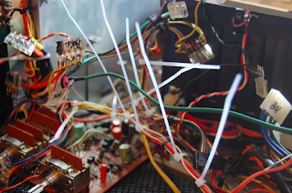
Due to the production standards all of the wire-harness were removed and restrung and new ties installed to clean up the chassis real-estate.
The original fan gasket is etched off and a new Filter material gasket cut and installed. the fan disassembled and cleaned witch can take a good hour + to properly do and lubricate.
Audio Notizen


No comments:
Post a Comment