
Marantz 2600 Monster Receiver


Today Im showcasing the restoration of an extremely rare receiver, the biggest receiver Marantz ever produced, built to topple the giant SX-1980, G-33000 and Technics Monster Receiver Wars…the Marantz 2600!

The 2600 model is considered one of the pinnacle in receiver designs by Marantz, cumulating the end of an era in solid state audio manufacturing and quality which gave rise to the unfortunate models seen in the 1980’s…. The Marantz 2500 and 2600 are very similar design, both employing the Hitachi scope display, robust power supply, massive toroidal transformers and the active cooling design for the large driver assemblies. The integration of the RF Quartz Lock added several circuits, the AF stage are almost identical in topology with minor changes employed.

P800 Power Supply
The Marantz 2500/2600 both employe a dual secondary winding for superior isolation and AC/DC conversion along with two multi-section 7200MFD capacitor. The dual sectional were both re-stuffed using 10000MFD electrolytic’s (Panasonic.) A higher voltage PS is required to drive the Hitachi CRT display as well.
One of the first points of consideration during the rebuild is the power supply regulators. All of the 313 type NPN regulators were replaced with modern, heavy duty On-Semi TO-220 MJE devices with new thermal compound and MICA insulators applied. Along with the regulators, both common cathode, common anode rectifiers were replaced with a state-of-the-art On-Semi TO-220 common cath/anode Ultra-Fast diodes with a 35nS soft recovery , low transistors and better dissipation. The remaining transistors were replaced with a modern, low noise PNP TO-92’s and a NPN TO-92L for better dissipation handling. The 4.7K adjustment pot was replaced with a precision Bourns type. Remaining 14V zener and general diodes replaced with modern axial 4148/14V500MW type diodes.

The electrolytic were replaced with high temp (105C) low impedance Nichicon PW unto 350V devices, remaining with an increase in operating voltages. All of the original mylar/PP were replaced
a high grade WIMA polypropylene film capacitor along with several resistors to carbon film 1/2W KOA type.


BEFORE

AFTER


P900 Scope Display & PD01 Scope Buffer (Hitachi 50TB31 CRT)
Powered from the high voltage Power Supply detailed above, the P900 assembly deals with some serious voltages for the Hitachi 50TB31 CRT display tube (200-500V+.) Many owners report a DOA or dead tube, this is often confined to failure of the regulators of JFET pair more than the tube itself luckily as these are incredibly rare tubes, often selling for $250+ itself.

Both sets of NPN regulators were replaced with a high voltage (350V) TO-220 regulators with new thermal compound and MICA applied. Both JFET 2Sk pairs were removed and tested along with scope calibration performed. All Pin connectors were cleaned and socket connections crimped again for a secure connection to the Hitachi.


BEFORE

AFTER

PD01 Scope Buffer
The gain/control PCB or Scope Buffer PCB allows for fine tuning the output display. The original mylar’s here are all replaced with a more reliable, high grade WIMA polypropylene film capacitor, two additional 2SK30’s JFETs are employed here.
BEFORE

AFTER

Soft Start Modifications
Similar to the 2500, many issues have stemmed from failed current limiting resistors in this array. This is often indicative of failed toroidal as well.The original design uses a 10OHM and 680OHM 10W wire-wound cement resistors to establish the soft start and in-rush handling. Changing the value and increasing the current handling is a must.


The two resistors were replaced with a 10OHm 25Watt and 640OHM 25Watt resistors using heavy duty propriety Brown Devil type Vitreous Enameled ceramic Ohmite resistors (one in parallel) along with a new 470MFD/100V Nichicon PW capacitor. A new industrial grade TE Connectivity KUP series soft-start was installed. These are very expensive but incredibly reliable relays.


PN01 Audio Muting/Protection
The 2600 uses a 48V DPDT relay to act as a disconnect during power cycling to protect speakers from harsh transients. A DC deviation control at the outputs shunts speaker outputs during out of phase responses and short circuits. The driver circuit contains the thermally reactive protection thermostats.
The timing capacitor were replaced with a low impedance, high temp (105C) Nichicon PW with an increase in operating voyages. The general 2473 diode was replaced with a modern axial 4148 type diode. The 667 NPN transistor was replaced with a modern, low noise heavier duty TO-126 NPN device by Fairchild. A new low noise 48V DPDT MY relay was installed as well.

BEFORE

AFTER

PX01 Peak Indicator
One of the unique definitions of the 2500/2600 peak indicator assembly is its versatility. More often than note, these peak indicator circuits can be misleading at best. The 2500/2600 indicator circuit was designed with the multiple impedances in mind and changes in AC supply voltage to the power supply (sags,etc…)
All of the small signal PNP/NPN devices were replaced with modern Fairchild devices including TO-126 and TO-92L forms for better dissipation as it sits atop the driver assembly. New Nichicon PW low impedance capacitors were installed with an increase in operating voltages. All the varistors and general 2473 diodes were replaced with modern axial 4148 type diodes.

BEFORE

AFTER


P700 Driver Stage and Notations on Heat Dissipation.
One of the unique features in the 2500/2600 receivers is the use of an active cooling system. A two-speed (idle/hi) fan is used through the activation of two thermostats mounted to the driver, one for idle current and the other as a protection stage shunting the outputs from the speaker output in cascade situations.
The fan is mounted between the driver assembly tunnel and the fan exhaust vent to the rear of the chassis. Marantz paid special attention to the design here as a high output amplifier generates hundreds of watts of heat. In standard passive cooling systems convection currents carry air passively over the heatsink plane and devices cooling the area. though through the convection dissipation a “boundary layer” of air develops between the heatsink plane and moving air, acting as an insulator effectively reducing the efficiency of passive heatsinks. Marantz’s use of a fan in conjunction with finned TO-3 mounted heatsinks to the base plane (main heat-sink) creates turbulence within the airflow of the tunnel and around the finned TO-3 mounts. This increases the effectiveness of radiant dissipation and negate any boundary air buildup over the plane.

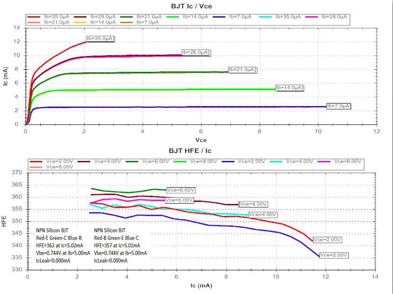
The 2600 driver is build upon the 2500 design with a quote “fully complementary symmetrical quadruple paralleled-array direct coupled circuit” The differential stage were replaced with a pair of 1% matched NPN modern low noise Fairchild devices (see curve comparisons below) and thermally coupled together, the constant current, pre-driver/drivers and all associated small signal devices were all replaced with modern low distortion/ low noise TO-92 and TO-126 Fairchild devices. Both offset and idle current adjustments were replaced with precisions Bourns devices. Several resistors were replaced with 1/2W carbon film KOA resistors and 2473 and varistors with modern 4148 type axial diodes.

Electrolytic capacitors were replaced with KT and Fine Gold audio grades, along with PW low impedance Nichicon capacitor with an increase in operating voltages. mylar and small ceramics were replaced with high grade WIMA polypropylene film capacitors. Couplers and .1MFD capacitors were all replaced with high grade MKP and Mundorf Evo Oil capacitors as with the recent 2500 rebuild.


BEFORE

AFTER


Differential Stage Mapping


P400 RIAA EQ
When this 2600 came in, the Mode Switch had the barrel end sheered at the potentiometer base, luckily a replacement was in stock here and installed.


New Switch Installed

With extremely low distortion output via a totally symmetrical topology. The P400 uses a series of dual differential stage, Class A emitter/class a emitter output stage. Both pairs of differentials were matched within 1% and replaced with a modern low noise TO-92 Fairchild devices. Electrolytic capacitors were replaced with a KT and Fine-Gold audio grade Nichicon capacitors with an increase in operating voltages.

BEFORE
AFTER


AF Stage PE01 Flat Amp
Unique in Marantz (typically BA series) the 2600/2500 uses a TA7136 Pre-Amplifier IC for an initial x9 gain stage driver. The TA7136 is a high quality integrated circuit with low noise, low distortion characteristics.

The electrolytic capacitors on the PE01 tone stage were all replaced with a KT and Fine-Gold audio grade Nichicon capacitors with an increase in operating voltages.Remaining 1MFD and lower value capacitors including mylar were all replaced with high grade WIMA polypropylene film capacitors.
BEFORE

AFTER


AF Stage PT01 Tone Stage & PS01 Tape/Monitor
The tone stage connects perpendicular to the PE01 tone amp stage with the balance slider connecting. along with a pair of differential a pair of 2Sk30 JFETs are employed.
Minus the Jfets, all small signal devices were replaced with modern low noise TO-92 Fairchild devices. The electrolytic capacitors on the PE01 tone stage were all replaced with a KT and Fine-Gold audio grade Nichicon capacitors with an increase in operating voltages. Remaining 1MFD, mylar and lower value capacitors including mylar were all replaced with high grade WIMA polypropylene film capacitors.

BEFORE

AFTER


PS01
The PS01 Tape Monitor stage features a simpler build that the Model 2500 series. The electrolytic capacitors were replaced with KA audio grade Nichicon capacitors with an increase in operating voltages as well as .33MFD to WIMA high grade polypropylene film capacitors. The .047 coupled film was replaced to a high quality Panasonic ECW polypropylene film.

BEFORE

AFTER

RF Stages
In addition to an increase output stage, the 2600 series receiver added the Quartz Lock RF feature and high quality dual MOSFET devices for linear operation and reliability, PLL and advanced NFB designs make for one of the more receptive RF stages seen in the Marantz receivers.

Main RF PCB

PC01 FM Buffer

PC50 Quartz Lock

PK Touch Sensor

Display Lamps
New SMD 8V LED's Installed along with both stereo/DLB and Scope Indicator. A New 47MFD Nichicon PW for the Function LED Indicators


Audio Notizen


Wow! Where did you find this treasure?
ReplyDeleteLike all the units published here on my blog I do the restoration for customers units not mine ;)
DeleteFantastic job, very impressive.
ReplyDeleteSweet! Even though I do not know what I am looking at, eventually I will learn something!!! It's fun!!! I think among other favorable results you produced a substantial clean db gain.
ReplyDelete