
Pioneer SX-737 Receiver

The Pioneer SX-737 was introduced from 1974 to 1976 and shared construction the 35/36/38 series. Unlike its class sibling the SX-750 the 737 features far superior build qualities and overall reliability versus single PCB oriented units. Boasting a modest 35-40W at .5% THDN which is perfect for most listening sessions and a unique dual use recorder option.


Power Supply AWR-057
The regulated power supply is comprised of a 3A bridge rectifier for the two 6800MFD rail filter capacitors and a half and full wave rectified source developing the 13 and 35Vdc -/+ rails.
Many manufactures were limited in power supply filtering capacitor sizes due to high volume/costs, today during the rebuild we can see major improvements arise from increasing the factory DC filtering stage electrolytic capacitors as we do in our restorations. Here the full wave/half wave stages and mains -/+ rails were all increased for better DC filtering with low impedance Nichicon PW capacitors including remaining electrolytic, all with an increase in operating voltages. As axial offer an inferior construction in my opinion to radials, the original 1000mfd form factor was changed to a modern radial foot print.

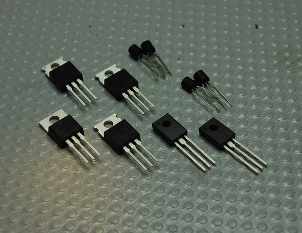
The 1A arrays were updated with Ultra-Fast, Soft Recovery Vishay diodes as well as 13/14V zener axial diodes. Small signal TO-92 devices were replaced with modern low noise Fairchild TO-92L devices with better dissipation. Both stand alone and thermally coupled TO-220 regulators were replaced with modern robust TIP devices, the thermally coupled TO-220 was coated with synthetic Wakefield thermal compound.
BEFORE

AFTER


Filter Capacitors
The 6800MFD bridge rectified dual rail 36V capacitors were replaced with computer grade CDE capacitors with a markable increase to 10,000MFD for better filtering and sub sonic frequency response.


-/+ Dual Rail Vdc Confirmation


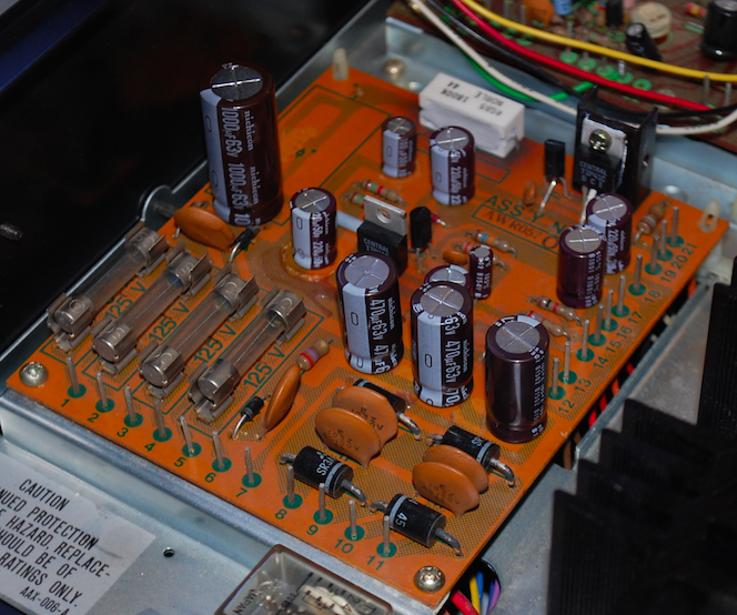
Protection AWM-025-C
The protection circuit in the 737 is shared across multiple SX series in A/B and C variants. The protection covers significant DC deviation across the output.
The electrolytic capacitors were replaced with a low impedance, high temp (105C) Nichicon PW with an increase in operating voltage. The series 330mfd capacitors were replaced with a single Bipolar 165MFD MUSE Nichicon capacitor ((C1XC2)/(C1+C2)tot). The .22MFD capacitors were replaced with a high-grade WIMA polypropylene type. New small signal TO-92 and TO-92L devices were replaced with a modern low noise Fairchild. A new non TO-126 low noise Fairchild was also installed.

BEFORE

AFTER


Pre-Amplifier AWG-030 & MIC Amp AWM-066
The SX-737 pre-amp stage consists of nf type, direct coupled circuit and a simple gain stage with attenuated dual sub/hi controls.
The electrolytic capacitors were replaced with low impedance PW and audio grade KT/KA Nichicons, operating voltages were increased and the initial dc filter capacitor was increased for better dc filtering. High-grade WIMA polypropylene films were installed. Small signal TO-92 devices were replaced with low noise, modern Fairchild devices.

BEFORE


AFTER


On the MIC amplifier assembler the low value capacitors were replaced with high-grade WIMA polypropylene film capacitors as well as electrolytic with low impedance PW Nichicon’s, a noted increase in operating voltages. New small signal TO-92 low noise Fairchild devices were installed.

BEFORE

AFTER


RIAA EQ AWF-011
A multi-stage, NF type circuit, direct coupled with a npn output stage with a report deviation of +.3dB.
Electrolytic capacitors here were replaced with a low impedance PW and audio grade KT/KA Nichicon capacitors with an increase in operating voltages.. High-grade 1MFD WIMA polypropylene were also installed. All small signal devices were replaced with modern, low noise TO-92 Fairchild devices.

BEFORE

AFTER


RIAA CURVE RESPONSE

Amplifier AWH-033
The amplifier stage in the SX-737 is built around a complete OCL type circuit, coupled input/output design. An initial differential gain stage and piggybacked bias compensating circuit and a pure complimentary 3rd-4th order stages. I do want to add however that the output rating of .5% THD is unrealistic as the unit is presented, their test must have involved isolating the amplifier stage, coupled as a AF-Driver receiver 0.9% THD+N is reasonable at rated output with a capable output of about 40Watts.
The differential pair devices here were replaced with precision matched low noise TO-92 Fairchild devices. New pre-drivers and 3rd order drivers were installed as well with robust, low noise TO-126 and TO-220 type Fairchild/OnSemi devices and thermally coupled with a synthetic Wakefield thermal compound. Precision Bourns bias and offset adjustment potentiometers installed.

Differential Matching

Electrolytic capacitors here were replaced with low impedance PW and audio grade KT/KA Nichicon capacitors with an increase in operating voltages. High-grade WIMA polypropylene film capacitors were also installed. New axial general 4148 type Fairchild diode installed.

BEFORE

AFTER


BIAS Confirmation@ 20mV


Amplifier Square Wave Applications with FFt (Fast Fourier Transform) Analysis
(*new verification report in our long line of extensive testing now included with restorations*)

RF AM/FM Front End
The RF front end was designed well in this unit, with a 4-gang variable capacitor, Dual MOSFET FM Front end and proprietary FM/AM IC stages. Also implemented was the PLL or Phase Lock Loop tuning. All of the electrolytic capacitors here were replaced with a low impedance, high temp (105C) Nichicon PW type with an increase in operating voltages.

LED's
New high quality Multi-SMD LED type Warm White 3-35K spectrum lamps installed.


AUDIO NOTIZEN
(Frequency Response/THD ~ Signal to Noise Ratio ~ Intermodulation Distortion (IMD) ~ Total Harmonic Distortion + Noise (THD+N) Thru Rated Specs ~ Clipping/Max Output ~ Av Gain ~ Separation (dB))

(Frequency Response/THD ~ Signal to Noise Ratio ~ Intermodulation Distortion (IMD) ~ Total Harmonic Distortion + Noise (THD+N) Thru Rated Specs ~ Clipping/Max Output ~ Av Gain ~ Separation (dB))

No comments:
Post a Comment