
Pioneer SX-3900 Stereo Receiver


The Pioneer SX-3900 was released during the early 1980’s along with the SX-D7000 series. The 3800/3900 employees a digital (FL) display for the RF and Audio output unlike earlier SX series and analogous meters. The driver stage is a complex NSA design with an impressive .005%THD rating!


AWR-210 Power Supply
The power plant in the SX-3900 Receiver employs a non regulated and regulated duel rail supply. The driver required 60-/+ rails are developed via a full wave bridge rectifier and two 15,000MFD filter capacitors, the regulated supply consists of a Full wave bridge 1A supply for the -/+ 54Vdc Driver, -/+ 32V Front End and -13V RF supplies. The 5.5V trigger is developed via a half wave array. The SX-3900 uses a pair of 2Sk FET transistors which are known to fail often in these designs, partly due the load application, the other from oxidization caused by the component glue used on local R/C and diode networks.
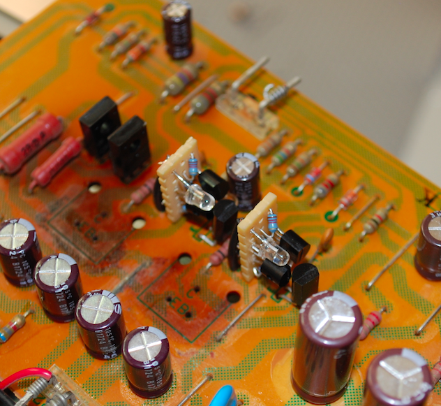
2SK34 FET Modification
Custom made, 2.2mA trigger source module made with 1% precisions films and low noise devices with two 2Vf green diodes. Replacing the failure imminent and prone FET devices.

BEFORE

AFTER
Remaining TO-220 regulators were all replaced with a robust, modern OnSemi devices, some coupled with synthetic thermal Wakefield compound. Remaining small signal devices were replaced with low noise, better dissipating TO-92L Fairchild devices. All diode arrays were replaced with Ultra-Fast, Soft Recovery axial Vishay diodes.


Electrolytic capacitors were all replaced with a low impedance, high temp 9105C) Nichicon PW type with an increase in operating voltage.

BEFORE

AFTER


-/+32 & -/+ 54V Confirmation


Filter Capacitors
The large 15KMFD filter capacitors for filtering the dual rail -/+ 60V supplies were replaced with new CDM Computer Grade 15,000MFD 80V capacitors, a new nylon insulated spacer was used for the appropriate chassis mounted bracket.

BEFORE

AFTER


-/+60V Rail Confirmation


AWV-008 Digital Display
The display for the SX-3900 is composes of fluorescent indicator tubes (FL Tubes) built into display assemblies. The peak indicator design uses a compensated circuit with multiple HA12010/TA718 integrated-circuits (IC). The RF display project frequency counts and Signal display also use a 5-point FL type tube display with precise feedback circuits.


The small value capacitors were all replaced with high grade WIMA film capacitors. The remaining electrolytic type were all replaced with a low impedance, high temp (105C) Nichicon PW capacitors with an increase in operating voltage. Both the meter calibration adjustments were replaced with new precision, sealed Bourns potentiometers.

BEFORE

AFTER


GWG-140 Tone Assembly
The pre-amplifier front end is quite a bit different than a lot of other Pioneer designs, focusing on a tight NFB circuit and a low noise, low distortion HA12017 Hitachi IC.
The electrolytic capacitors here were replaced with a audio grade KT/KA and low impedance PW Nichicons with an increase in operating voltages. The DC 32-/+ coupling films were increase for bette filtering. Remaining small values and mylar were replaced with high grade WIMA polypropylene film capacitors.

BEFORE

AFTER


AWM-226 RIAA (Phono)
The simplified phono stage in the SX-3900 is quite accurate after plotting (see below report.) Using a PNP differential and bootstrapped voltage gain stage to a SEPP output.
The electrolytic capacitors here were replaced with a audio grade KT/KA and low impedance PW Nichicons with an increase in operating voltages. The DC 32-/+ coupling films were increase for bette filtering. All remaining small signal devices were replaced with a low noise TO-92 and TO-126 type Fairchild devices.

BEFORE

AFTER


RIAA Curve Response

AWH-097 (Pioneer SX-D7K Driver Design)
The driver designed referenced in this serial edition is used on the equivocal SX-D7000 receiver with more digital features. The SX-3900 uses a complex NSA designed amplifier stage. The dual differential front ends with a current mirror pushups stage. The pre-driver (darlington configured) also employs a constant current source for high gain development. A high-speed bias servo control circuit is employed with a 2-stage darlington SEPP output design completed with a NFB circuit.
The initial dual devices were all beta matched and plotted together with new low noise TO92 Fairchild devices. All of the driver stage TO-220 devices were replaced with robust OnSemi modern drivers, thermally coupled with synthetic wakefield compound. All the bias and offset potentiometers were replaced with a seal, precision Bourns potentiometers.


Differential Mapping


All of the electrolytic capacitors were replaced with a audio grade KT/KA and low impedance PW Nichicons with an increase in operating voltages. Remaining electrolytic and films were replaced with a high grade WIMA polypropylene film capacitors.


BEFORE

AFTER


New Output Device Connectors Installed
One important notation is the output device mounts, these are made of a frail plastic, due to its proximity to the skilled heatsink, radiant heat has baked the plastic mounts to a detriment. These often at this point are broken and have very little grip to the retention clips. A new heavy duty, robust mounts were installed for each output device.
BEFORE

AFTER


Bias Confirmation


RF
The RF front end is a marrying of analog and digital display. The FM front end uses a 4-gang variable capacitor and MOSFET RF stage amplifier (HA1201 IC), also with the quartz-lock system design. The Am design uses a 2-gang variable capacitor and a HA1197 IC RF amplifier and AGC circuit.
This is the largest assemblage is the SX-3900 with a single footprint for each stage. This stage is easier once the chassis is entirely tore down. All of the electrolytic capacitors in this stage were replaced with a low impedance Nichicon PW type with an increase in operating voltage. The small value electrolytic were all replaced with a high grade WIMA film capacitors.


LED's
With the display being a FL tube, the highlighted display area is illuminated by three lamps, these were replaced with a custom multi-SMD LED type lamps.


AUDIO NOTIZEN


Noah, great job on my SX-3900! A very extensive analysis of the restoration process and current specs. Bringing back this classic Pioneer receiver to "better than new condition" is fantastic, and requires a lot a specialized skill. Thanks for all of your work on the project.
ReplyDelete