
Marantz 1200B Integrated Amplifier


The Marantz 1200 and 1200B are very similar designed integrated amplifiers with minor form factor differences, such as the bridge rectification location on the A8 assembly in the 1200. Both series heavily emulate the Marantz 240/250 amplifier designs. These have a pre-amp stage similar to the 3XXX series X10 gain designs.


A7 Regulated Power Supply W/ Hex Upgrade
The power plant of the 1200B is divided between a full wave bridge rectifier suppling 73Vac ( / 1.414 @53V-Vf = 52Vdc) with two 20,000MFD capacitors. An additional full wave bridge rectifier located on the A7 PCB regulates a dual -/+13V zener/NPN/PNP supply for the AF and RIAA front ends. The rails are fed to the Main PCB which uses slotted connections for the proceeding Af front end PCB's, two .15MFD capacitors on this stage were replaced with MKP and bypassed with .47MFD WIMA polypropylene films which the controls were cleaned.
On the A7 assembly all of the axial electrolytic capacitors were replaced with a high-grade, high tolerance Sprague Atom axial capacitor and increased to 500MFD standardize. The Full wave bridge was replaced with state of the art, MUR series HEXFRED ultra-fast, soft recovery devices. The NPN/PNP regulators were replaced with modern TO-39 devices.


BEFORE

AFTER


Filter Capacitors
The main 6A bridge rectifier was replaced per diode with a ultra-fast 6A 200V axial diodes and new 5W MOX type 2.2K resistors across each filter capacitor. The 20,000MFD capacitors were replaced with computer grade Nippon’s increased to 22,000MFD at 80V.


BEFORE

AFTER


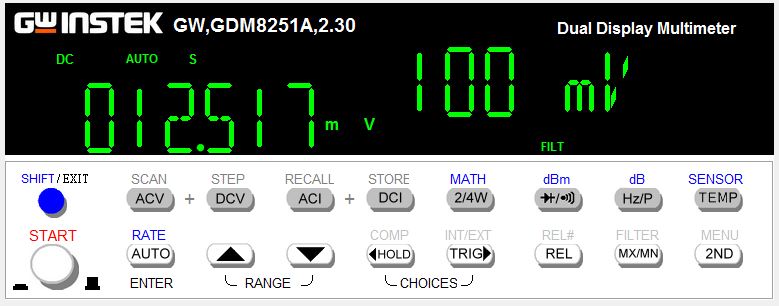
-/+ 52Vdc Rail Confirmation


A8 Protection
The integrated protection allows for a soft/start inrush protection. Protections also incorporated was significant DC deviation and ultra low subsonic 10Hz oscillation. The new Omrons used in these designs require a modification of the coil tap. In this case the PCB itself was remapped for easier repair in the future.
As mentioned above, the relay was replaced with a fuse indicator modern Omron MY series. All of the axial captors were replaced with modern radial low impedance Nichicon PW’s with an increase in operating voltage. The full wave array was replaced with ultra-fast, soft recovery Vishay diodes. The SPS/SS devices were replaced with modern, low noise TO92 and TO-126 devices with better dissipation.The original wire-wounds used in this series tend to suffer environmental breakdown of the substrate, new wire-wounds were replaced and R711 adjusted for a vF require on the new indicator LED installed.

BEFORE

AFTER


A2 Phono/RIAA
The phono stage is comprised of a single ended differential stage, inverter and emitter follower output design with a gain of 40dB. The RIAA is a R/C network.
Both of the clipping pots were replaced with precision, seal Bourns potentiometers. The differentials were replaced in pairs with high gain, low noise modern BC devices and a low noise TO-126 fairchild device. Input, coupling films were replaced with high-quality polypropylene films and WIMA polypropylenes. Electrolytics were replaced with low impedance PW and audio grade KT/KA Nichicon capacitors with an increase in operating voltages.


BEFORE

AFTER


RIAA CURVE RESPONSE

A3 X10 Amplifier
Similar to the low-level amplifier design above, the X10 gain stage employs a single-ended differential gain stage andNFB design with a nominal output of 20dB with the integrated tone control.
All of the small signal devices were replaced with high gain, low noise ZTX and Fairchild devices. Electrolytic capacitors were replaced with a low impedance PW and audio grade KT/KA Nichicon with an increase in operating voltages. Films and ceramics were replaced with high grade WIMA polypropylene film capacitors.

BEFORE

AFTER


A4 Tone Amplifier
The Tone amplifier stage has a unique bypass feature, with the tone switched “IN” the X10 signal is applied to a gain -/+ switch and feed via the tone amp thru a single-ended differential and inverter design. With the tone “OUT” the X10 stage is feed directly to the gain level switch.
Like the X10 stage all of the small signal devices were replaced with high gain, low noise ZTX and Fairchild devices. Electrolytic capacitors were replaced with a audio grade KT/KA Nichicon with an increase in operating voltages. Films and ceramics were replaced with high grade WIMA polypropylene film capacitors.

BEFORE

AFTER


A5/6 Symmetric Driver Assemblies
The core driver design uses an initial emitter-follower/current source feed to the differential amp, each coupled to the pre-driver/driver output stage with current sensing arrays incorporated.
The differentials were matched and replaced with low noise, high ZTX devices,thermally coupled with sythetic Wakefield compound, current sources were replaced with low noise modern, TO92 Fairchild devices. Like the above mentioned resistors in the protection stage, the driver stage emitter ballast exhibit the same issues and were replaced with new wire-wound .15 ohm resistors. The bias and offset potentiometers were removed and cleaned, due to their fabrication and current capacity I recommend retaining them.


Differential Matching

The electrolytic axial capacitors were all replaced with low impedance PW Nichicons with an increase in operating voltages, associated films including the input were all replaced with high grade polypropylene type including MKP and WIMA.

BEFORE

AFTER


Bias Confirmation


AUDIO NOTIZEN


No comments:
Post a Comment