Friday, November 6, 2015

Aker's Marantz 2265B Receiver

Marantz 2265B Receiver 


Id like to showcase this rebuild. I was extremely happy with how it turned out, cosmetic and performance wise I was just blown away. both hi and low level stages are crystal clear yet pronounced for each input. I really like the high level stage for line level devices such as my MicroMega CDP. I was lucky enough to have a Thorens TD160 to audition this with as well :)

This is an Audiokarma members unit, Arrived in quite dirty shape with oil smudges all over the faceplate and finger mares. Also noted was the unit was stuck in protection with a host of driver issues.  In this case the 3rd stage drivers and final output devices were shorted along with the bias array resistors. All new outputs were ordered for this overhaul.


Power Supply P800
The power supply is a little different here than in per-say the 50-70 22XX series. I would suggest attacking this board as one replaces the filter capacitors and removal of the driver stage, this allows you to contort the board in a open-book fashion. A new MY4 Relay was installed with OS cover, this particular relay is easy to replace in this supply as the tracing is easily accessible. All the lytics here were replaced with my standard high temp, long life rated Panasonic FR/FC capacitors. 


Also updated were the common Anode/Cathode devices. MicroSemi manufactures an extremely reliable 20A/200V Ultra-Fast TO-220P packaged rectifier to replace the originals. Its important, while your in here to remove the caustic glue used to support the larger lytics.


Driver (Single Topography) P700
Normally I'm not a big fan of the single topography PCB's like used in the 2265B driver stage, though in this case the layout is very symmetric and clean with totally separated rails and return, they way it should be done, if done, unlike per say the 2252B which houses the PS and Driver  stage all on ein PCB.


All the lytics here were replaced with audio grade Elna's and low impedance, high reliability Nichicon PW's. Differential pair transistors were updated to Hfe matched 992 BJT's and all general and rectification diodes updated to UF applications or general 4148 type. Also updated were glass pack diodes to 4148's soldered in series All new outputs and MICA were installed, reliable modern outputs cross referenced to MJ21193/94G devices.


The damage consisted of a shorted resistor at R772, the final stage Q759, Q757 was shorted along with outputs in that bank. 243G MJ' were replaced in the final stage along with 2690ays for the the Q757. 


New 35mm 10,000 microfarad CDE capacitors were installed these have been my best find since Panasonic THA's became less available. When the driver board is removed is convenient. They also share a common ground strap like many of the higher rated 22XX's do. I like to add the new EG1018 7A power switch and a Vishay X1Y2 safety capacitor after the filters to finish up on hardware. 

Phono P400
The phono here shares the same PCB as the switching control assembly as is in many later 22XX series Marantz, I prefer the stand alone PCB. Though they did get away from the faulty 458 transistors like the earlier models. All lytics here were replaced with low impedance, high reliability Nichicon PW's. I recommend reflowing the control connections at this time as they appear to suffer excessive torque from the switch when in use. Remember when replacing to save the leg dressings as a few lytics need to be contorted to allow for the shaft of the selector switch.


Pre-Amplfier/Tone PE01
I like these assemblies, not as easy to access as say the 2325 with that molex. All the lytics here were replaced with again Nichicon PW's and audio grade KA's by Nichicon, along with bypass polypropylene WIMA and coupling MKP polypropylenes. This is the perfect time to clean and treat phenolic based potentiometers as well. 


RF Stages
I really like how the main FM stage is accessible under the chassis, which makes recapping this section easier than most units as they typically sandwich these boards. In any RF stage, AM or FM I like to use the PW's again. Low impedance and very reliable they are perfect suitable here. 


I was very happy with how clean the faceplate and knobs turned out on this unit, Overall I'm quite blown away with the 2265B, after the overhaul it really sounds amazing, clear and precise are the two words that come to mind. 


Monday, November 2, 2015

Sansui G-7500 Highlight

Sansui G-7500 Receiver 


We have another G-series Sansui in for a repair I thought Id highlight again, this time i'm featuring the G-7500 model.

This unit came in with catastrophic damages! A fire had erupted on the F-2980 assembly under the bias network and blown the right output bank. Again, the culprit is the F-2980 area, we have many many Sansui G series come in with major damage to this board. The topography is similar in most of the 7500-8000 series with minor output and filter differences. Also different in the 7500 is the output bank assemblage. The 7500 uses again TO-3P type packages but with typical packages emitter resistors, the heatsink is also more similar to the G7700 on up units, utilizing a solid block heatsink fitted to the chassis as shown later in this write up. 

Pulled TO-3P Output Bank F-2981/2

F-2980 Damage
First noted was significant repair of damaged PCB tracing from a prior technician to the other channel. Thats why its important to be familiar with aged units, certain soldering and heat precautions need to be taught and developed. Also was the repair and debri removal of the burnt PCB section. Etching new tracing and flushing the board with 99.99<% iso alcohol helps remove old flux and stains to give a cleaner working surface, its also necessary when adding new eyelets to PCB.

Damaged PCB


Cleaned PCB


The damage to the final, and associated BJ-transistor devices was significant, I noted both NPN/PNP TO-3P outputs confirm what I suspect of being shorted along with the R70/71 .33 5W emitter resistors, again these are mounted on the actual F-2980 footprint unlike some of the other G-series which located them to the output device PCB assemblies 2981/2.  The damage then extended to  TR19 which is a readily available 992fbu BJ-transistor, actually blew the silicon package apart! Next we tracked down to the stabilizing resistors and bias array which had all the 1/4W resistors actually blown and burnt apart, along with a 1/2W 10ohm. As is typically the 1st stage FET differential and 2nd stage pairs where intact and fine. This particular fault took out the 100ohm bias potentiometer as well, which is important to notate, this shows significant draw. 

Damaged F-2980 (Notate Burns!)


New coupling lyrics were replaced along with 1/2W MOX and carbon film resistors and new 5W wire-wounds, the bias potentiometer was replaced with a 500 ohm single turn precision pot along with updating 2473(4148) general type diodes.


Repaired F-2980


As a pre-cursor on the F-2980 assemblies I replace the lyrics with high temp long life FC/FR or high temp PW's along with removing and cleaning the caustic glue from the board.  Watch the outputs and monitor with a 1K sine and re-biased/offset adjustments were correct.


I also wanted to note the different lamping used in the 7500, this models uses just two 8v globular incandescents behind the meters for the entire display, about a thousands time easier to replace in this model. 


Wednesday, October 28, 2015

Pioneer SX-3800 Receiver

Pioneer SX-3800 Receiver 


Here we have a nice Pioneer SX-3800 Receiver. Produced in early 1980 the 3800 was a mid level 60 w/Ch two channel unit, incorporating non-switching/linear driver stage and quartz lock tuning and a modest 24,000 microfarads of filtering and an impressive THD @ 8 ohms >.005%. The 3800 shares similar looks still to preceding SX series with likewise RF single pcb topography. A lot of fans out there of the 3800, it drove our pair of Rti 6 like butter. My biggest impression was the smooth transitions present in the lower response ranges, effortless. 


Power Supply Assembly
Here is where my major qualm resides with the SX-3800. The driver/power supply pcb's sandwich a very thin/ finned style aluminum heatsink. The bias applications happens to run pretty damn warm on these and that heatsink is close to useless. Also, it should be noted that the foil sides face each other, relating to obvious radiant heat issues baking the joints.  Like wise the main 12,000 microfarad capacitor clamps when tightening have a small pitch to the lower flange, this contorts pressure on the joints, along with the heat and you have issues. Doing a little research on the various forums I found several other users notate the same exact issue. You will especially notice because it reduces the ac filtering, allowing an obvious AC hum into the mix.


Noted AC on hum our Tektronix 2215A scope


The lyrics here were replaced with high temp PW's and Panasonic FC long life high temp capacitors, along with ultra fast/general 4005/4148/5248B diodes. Its important to remove all the glue forming around resistor leads and capacitor seats. Some folks have updated the SR3AM diodes but I've never come across faulty ones myself.  I should note its much easier to open-book the assembly after removing the Pformer. 


Driver / Protection Assembly & A note on non-switching A/B design
The lyrics here were replaced with KT/KG Nichicons and low impedance coupling 1uf PW's. The 3800 uses a pair of dual body differential pairs (BJT). Updated were general 4148 diodes and final stage 15032/33 OnSemi's.  Also interesting to note is the utilization of non switching A/B operation via high-speed DC servo bias. This runs the driver stage with no real "On-Off" stage. As current is increased in one output device it is decreased in the other but limited (near 0 zero) due to non-linear occurrences, hence the reaction is much quicker because the device is not reversed bias such is typical in class A/B operations (on-off).


Tone/EQ Assemblies 
All the lyrics in these locations were replaced with low impedance PW's and audio grade Elna Silmic II's. When performing work on the tone assembly its best to work from top-down, removing and opening the display PCB and removing the plastic arm for the function controls. These are long angle plastic brackets so be very careful and make sure you place them prior to closing the top PCB. Now is also the time to douse and clean the phenolic potentiometers and switching type  controls. Its important to note many 3800 users have notated RIAA issues to  damaged HA12017 IC's. 


Opened Control PCB 


HA12017 Hitachi IC Note
This particular IC is used in the RIAA EQ stage and Non-Feedback pre-amplifier topography. The HA12017 was a convenient smaller package introduced (SIL) for PCB designs. With excellent low noise characteristics its a fairly reliable low distortion IC with impressive RIAA applications (OP Gain <=105dB)


RF Stages & Control Assembly
The RF stage incorporates a 3 ganged FM and 2 ganged AM tuning capacitor with a AM centered HA1197 IC for AM stage control, in junction with a 5 digit PD5009 counter controlled fluorescent display. The 3800 also involves the quartz-lock feature for stable frequency, active compensating  control to minimize drift and ensure reception. All the lyrics here again were replaced with high temp low impedance PW's for reliability. 


Control Assembly


All in all the SX-3800 sounds phenomenal short of a few minor manufacturing changes I would have made, a very nice unit. Hefty with some weight at 35lbs it retains that classic era look with reliable 1980's modern advances. 


Saturday, October 24, 2015

McIntosh MA5100 Spotlight

McIntosh MA5100 Integrated Amplifier 


We had a pretty ruff McIntosh MA5100 come in a few months back after bearing some rough Wisconsin winters. The chassis had yet only minor pitting evident with the screen printing all intact and undamaged! The MA5100 was a integrated two channel 45 watt/CH sold in the late 60's to early 70's. Amongst McIntosh fans of even the neediest requirements, the MA5100 is held in regards by many.  I wanted to highlight the PCB sections here beyond the cap stuffing.


Pre-Amplifier PCB 043-723 & Filter 043-722 PCB
One thing I like about these MC's is the use of quality Mallory axial capacitors. Typically axials seem to be of inferior construction compared to their radial counterparts so finding a capacitor with high expectations an be tricky. I like the TVX axial offered by Nichicon but in this case I decided to go with the Sprague ATOM axial series which is a low leakage high quality long life axial available from 6V-500V. After trying several MKP and WIMA PT and PP type I settled on using Panasonic ECW polypropylene type films for the rest of the stage with impressive results and sticking with carbon comps.   


Like the symmetric pre-amp design, I decided with the filter assembly to utilize ECW's polypropylenes again and carbon comps. Whats nice is the ease of access here, undoing the standoff screws you can open-book the PBC's forward, this also gives you great room to buff the chassis here without depopulating the entire chassis. 


Drivers 043-724
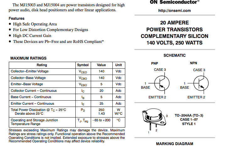
The driver sections are a fairly simplistic push-pull topography. Again I went with Sprague Atom axial capacitors with a polypropylene ECW compliment, I preferred the ECW's to say the MKP's I use in Marantz pre-amps. The differentials pairs were mismatched due to a repair in its history so matching Hfe On Semi BC556 were utilized in place. Also noted were mismatched output devices MC#132-513, On Semi manufactures some excellent replacements MJ15003 20A/250W BJT devices.

MJ15003


PCB Assembly 043-724


Auxillary 100/200 microfarad Mallory caps for the coupling/drivers outboard were replaced with Sprague Atoms and .01 microfarad PT type ECQ' Panasonics. New #1864 bulbs were installed while we work on a proper 28V LED replacement with proper disbursement. I'm a big fan of using Flitz polish for points around the can cases, knobs and RCA buffing. Sometimes short of re-plate theres not much you can about pitting but prevent further oxidization.


I was quite impressed with the final product and will be looking forward to another, it paired quite nice with an array of speakers we tried. Each stage seems to consistently blend well with no significant lower end lag or top out. 


Saturday, October 17, 2015

Adcom GFA-555 Rebuild II

Adcom GFA-555 Power Amplifier 


We received another GFA-555 with blown outputs a few weeks ago, so new output devices and a driver board overhaul were due.

As I've mentioned before in a posts the GFA-555 is an incredible Adcom amplifier. Released in 1985 it touted a stable 200+W/CH @ 8ohms w/ THD @ .003%. A overall capacitance of 60K microfarads with a 700A torodial in the chassis, rated dampening at 900<+, direct coupled topography  and initially under $1500.00! 

The GFA-555 is one natural amplifier, I had initially expected some slightly muddled response or at least..breathy. But before and after an overhaul the unit produces exactly what you want, amplification with no noted flubbered attenuation,clean power.  Im not impressed again with the Adcom pre-amplifier pairs but thats another story.

I took a similar approach to the driver assembly. The differentials in the first stage utilize common emitter 2SC2240 BJT-'s which are a great compliment, I like to use some matched 1845's for longevity and peace of mind. All electrolytics were replaced with low impedance high temps rated at 100V, I used a WIMA PP and ECW PP films in place of the originals and replaced all general 4148's again for peace of mind. The GFA-555 has a very reputable biasing circuit due to the implication of a mirror voltage circuit. 


Constant Current notes;


The GFA-555 has such a stabile bias because the main output devices (Q13-Q20 NPN/PNP) in connection with 3rd stage Q11/12 emitters to help create a simulated circuit through R19/20 to Q9/10 which establishes a constant current at R21. This is achieve through matching the devices with Q11/12 creating an established Iref (Current Reference.) Below is a standard BJT mirror bias diagram for references. 

GFA-555 BIAS DIAGRAM


EXAMPLE