

Here we have a little Kenwood KA-5002 Integrated Amplifier. The KA-5002 gets a lot of high remarks from Kenwood-Trio fans out there. Rated at a modest 30W/8Ohm (48W/4Ohm) @ .5% THD (20Hz-20Khz). The KA5002 is a classic direct coupled designed with total symmetrical complimentary driver stages. It also includes a useful RIAA impedance selector and uber low level phono input and balance NULL features for zeroing.
This unit came in , in a sort of state, an audiokarma member had attempted a restoration. This is why very important to do your research and practice technical skills…or better yet, hire a professional to save a large repair bill.
This unit would not come out of protection nor would it bias or adjust dc deviation correctly. Faults had been narrowed down to the driver + stages so Ill jump right to the drivers. Another issue we came across after initial repairs during a bench test was the unit would trip its protection at exactly 753mV output.
I should note an updated bulletin denotes that 3X driver PCB configurations are prevalent on the KA-5002 and they are NOT interchangeable as they include a separate protection assembly or assimilated one. This is SB#2006 INCL ( Before S/N 240001, from 240001 and from 43001)

The following describes (From 430001 PCB # X07-1020-00)
The first item notated was improperly cross-referenced Bipolar Transistors. Final stage 2SA/SC497s should be replaced with TO-126 1220/2690 PNP NPN type, also noted were the dual differential pairs 2SA493 which work great with KSA992 standard small signal NPN BJT's. I suspect from over current in the final stage during the customers operating stage damaged ensured to the VRe2 bias potentiometer, all of which in this unit were replaced with heavy body type. Also noted were leaky 2SC627 TO-39 type NPN's, which I thought odd. A new correct 100/50 capacitor was replaced as well. After initial biasing test and output we later found that 4.7 ohm resistors had been installed versus 0.47 ohm 3W resistors. New emitterwiderstand were installed and bias compensated (.33x2).30mA(19mV Bias)


As noted on the SB2006, this driver incorporates the protection as well (Qe13-18). Diodes D2-4 were updated to 1N4004 type rectifiers which are damn near impossible to blow. It was noted that 2SC983's (Qe13-15) was improperly cross-referenced and changed to 1845 BJT's. Qe16 was updated to a modern TO-220 vs the original TO-39 package with a MJE350. An entire diode network of 1S1555 to 18K doesn't exists on the update SB2006 on this pcb but is present. There is also discussion on the 10D-1 Diode and discrepancy between data sheets, I believe its a (1.5)2-2.5A 600V diode at minimal, in some applications the 400# family diodes may suffice. Also noted were missing R48/49 from the restoration attempted, these were replaced with carbon film 1/4W 680 ohms.
The relay was noted to be wired incorrectly shunting the DC to the coil contacts on the same relay sides which was re-wired correctly and a LY installed. The 2,200 microfarard filters were increased to 4700 microfarad Super-T' (Gold) Nichicons and all adjustments remade and confirmed, an update 3A/600V diode to the 1000MFD was replaced.

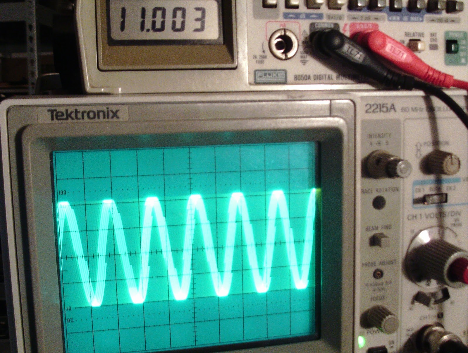
Below are some final output rating for a stress test with precision 4.25 loads. As you can see were about 1% within dBm
500mV 1Khz Sine beim 4.25 LOAD
Links
4.80mV 5.42W (37dB)
7.02mV 7.02W (40dB)
10.38mV 25.35W (44dB)
Recht
5.02mV 5.92W (37dB)
7.40mV 7.40W (41dB)
11.00mV 28.47W (44dB)
No comments:
Post a Comment