Sansui 1000A Tube Receiver
We had two Sansui 1000As come in recently, one with a bias rebuild we did a few months ago back for a full restore as well as the other. The 1000 came in a transistor and valve topography, with the 1000A being a very collectible receiver. Rated at a fairly modest 40W/Ch using a compliment on each channel of two 7591 power valves. The clincher Sansui utilized with the 1000A is the use of MASSIVE high quality Hashimoto Electric output transformers, Hashimoto started in 1958 and lead its production facility to almost exclusively Sansui at the time. Today Hashimoto has delved into their own series of HiFi valve amplifiers. I cleaned and work the tracking on the existing potentiometers, if you have any trouble tracking replace with a 10K multi-turn instead.
Output Stage (7591)
An interesting thing to note on the 1000A series are the variants of the bias circuits implemented. Several biasing configuration are out there using a series of one, two or four bias potentiometers to bias a pair of individual sockets. Both of these comprise of the independent pot design, which is better as we can dial in each specific tube. As I highlight in our past 1000A posts its important to add a 1/4W 10 ohm resistor from the cathode (pin 5) to ground of each 7591 valve, this gives you an added protection of destroying the resistor first shunting the tube and a stabile bias parameter. using our bias formula and the 7591 dissipation factor were looking at about 32mA each cathode or 325mV across the resistor (325/10) 32.5mA
Dual Potentiometers
Quad Potentiometers
Present in the 1000A are tons of oil-type electrolytic capacitors which are well known to be failure prone if not actively failing at this point in their life due to the inferior construction of axial oil-type of the period. All the 1microfarad and larger values were replaced with quality Nichicon TVX axial capacitors up to the 250V+ rating components. Electrolytic in the bias stage were replaced with 630V polypropylene Solens and accompanied resistors replaced. 1microfarad and smaller oil-type were replaced with high quality Panasonic ECW polypropylene film capacitors from .00047 to .1MFD.
form fitting new axials
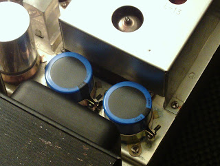
Nichicon were used for the filter cap replacements on top and stuffed cans with 40mm diameter. The 40mm 220/220V capacitors had their respective SW-05 diodes updated to 1.5/700V UF4007 diodes in parallel with a .0051 film capacitor along with the isolated SW-05.
SW-05 Updated
New 8-pin octal sockets were install for all four 7591 power tubes. The rear RCA’s connectors with buffed along with the OPTs removed and chassis buffed at specific points as shown, the end result was phenomenal, almost mirror like!
Before
After
Buffed RCA Inputs
I was incredibly impressed with the end result, with the bias dialed in on matched 7591’s and the oil-type removed the 1000A will continue to be as reliable as can be with plenty of power, very smooth yet deep sounding.
Our Test Station @ Hallo-Fi
Audio Notizen (results)
Pin cathode bias beim 10Ohm final*
ein 322
zwei 325
drei 325
vier 325
10Khz beim 8Ohm
Recht
3.13V 1.12W (30dB)
4.98V 3.10W (34dB)
10.17V 12.92W (41dB)
16.57 34.32W (45dB)
Links
3.36 1.41W (31dB)
5.20 6.36W (38dB)
9.0 10.12W (40dB)
16.26 33.04W (45dB)
5.20 (6.36W) (38dB)
9.0 (10.12W) (40dB)
16.26 (33.04W) (45dB)


Nice work!
ReplyDeleteFantastic job. Thank-you this is very helpful info for me in the middle Of a 1000a restoration job.
ReplyDeleteFantastic job! This so helpful to me being in the middle of a 1000a restoration myself. It will encourage me to go deeper into my restoration process.
ReplyDelete