Friday, November 28, 2014

Marantz 1070 Integrated Amplifier


Marantz 1070
Heres a real early commission of a Marantz 1070 integrated, a neat design on a model you seldom come across.


P800
Silmic II's and a FG were used on the power supply from a recommendation on this particular unit,H801 was a common cathode MUR1620 diode, where a 131B was. The, Adjustments were made at J810 & J811 adj. R807 to 40VDC initial 41.00V Reset to 40.00V. As much of the glue and so fourth cleaned off nicely.
A new EG1018-ND switch was placed with the safety cap across.


PE01
I used my typical assortment here, Nichicon muse for the bipolar's and WIMA's in place of the tantalums along with Silmics, again I recommend keeping the large brown films, unless a must some ECW PP's there. I think these selections really have some harmony here.


P400
Silmic and WIMA's were again used here with transistors to bother on this model, a slight variations from the 845's with 0.00ma leakage and testing well.


P700
The removal of the amp board can be tricky, but I found if you have the heatsink mounted SVT diodes and unscrew the rear panel you gain an easy access point. Silmic/WIMA and FG's were used along with a special Elna Cerafine, these are very nice, albeit pricey electrolytic. The bias and offset have pretty easy tap locations as well. New thermal compounds and mica were done as well just to freshen up the old stuff.
Idle Current Adj.
J714 & J716 adj. R733 to 10mv initial 10.5mv Reset to 10.00mv
J715 & J717 adj. R734 to 10mv initial 10.00mc Set
DC offset
J723 & J722(G) adj. R711 to 0.mv initial 5.0mv Reset to 0.00mv
R724 & J722(G) adj. R712 to 0.mv initial 3.5mv Reset to 0.00mv


The Main filter caps have a unique location mounted under the chassis on this model, these were replaced with two 10000uf 50V 
647-LKG1H103MESCBK Nichicon KG's. The higher capacitance leads to us to a more refined and deeper lower end.


A blue LED replaced the original yellow incandescent to give that typical  blue Marantz to match the owners Model 150 Tuner. 


N.S.

Marantz 2220B Receiver


Marantz 2220B

This is kind of a touch and place restoration, with selective boards. A nice open model to work on, with a symmetric amp PCB. Was quite blown away by this little model, though Im not really a B variant fan. 


P800 Power supply
I've been really favoring the Panasonic FC's and FR's now in the power supply, their robust, and rated well. H803/H804 the 131B/ 132B diodes were replaced, the 131 with a common cathode MUR1620 and the 132B with two UF4005 common anode.. H808 s1b-01-02 was replaced with a s ingle UF4005. Voltage was adjusted at J811 & J812 @ R808 to 35VDC.


P700 Amp Board
All the lyrics here were replaced with either Silmic II's or FG's. H705/706 MV13 were replaced with two 1N4148 diodes in series and shrinker, and the differential pair of H701-H704 were replaced with matched KSA992's, greased and shrinked.
This unit is literally so pristine I even doubt its seen many hours judging by the switch and relay, so the relay here was only cleaned at the contact, but its a LY-02 Omron type. Set idle per channel at 20.4mV Left and Right with offset at 0.04 L/R and stable as can be. Runs quite cool even at an hour or two.


P500 Tone Board
Lytic's here are Silmics II's, at CE23/24 Nichicon MUSE ES bipolar are used. With WIMA MKS2's used at CE19/20 and CE 21/22.


P400 Phono
Lytics again here were replaced with all Silmic II's, the two tantalums C401/402 were replaced with WIMA MKS2, the BJT's here are fine as is.


New mica and thermal compounds were applied along with a new EG1018-ND dpdt switch with a vishay X1Y2 safety cap.


N.S.

Thursday, November 27, 2014

Marantz Model 30 Integrated Amplifier

Marantz Model 30
Grabbed this for my personal use, got lucky a bit; this particularity model having a serial of 1640!  The Power supply, relay and amplifier boards are all very similar to the model 15. 32 and model 33 pre amplifier. Originally these use 2 channel moto outputs, very robust unit at 120W total RMS.

Im really a huge fan of symmetric isolated board topographies, and the assemble is very straightforward with most boards or clamps being fairly easy to access along with test points. the only major draw back was the U shaped chassis, which doesnt allow you to remove the back panel as its a folded chassis.


This unit had suffered a catastrophic cascade failure of the amplifier channel, protect and PS boards. Heres an outline to my method.


The primaries and secondaries are not shorted so we add first the the power supply board to the primaries;

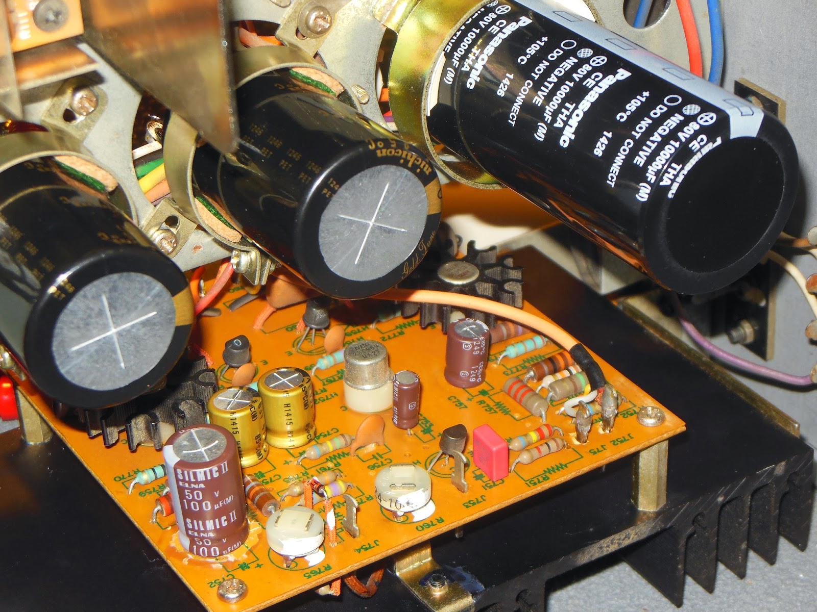
At the power supply pin 1 and 9 were noted to have crisped traces causing intermittent connection, Along with C404/405 venting excessively.
The Diodes CR401-404 are all general purpose 1.5a rectifier diodes. Q401/402 I believe helps regulate CR401-404 diode bridge. The manual states
zeners CR405/406 are the voltage references for the two transistors. All the transistors and diodes were updated and the electrolytics replaced with
quality axials.

CR401/404 1.5a rectifier (512-1N5393) IN5393 equivalent (common)
CR405/406 18V 500mW zener (833-1n5248B-TP) IN967A equivalent (common)
Q401 BJT NPN (512-KSC2690AYS) SPS2219 equivalent
Q402 BJT PNP (512-KSA1220AYS) SOS2220 equivalent
c401/408 500uf 25v
C404/405 100uf 50V
C409-412 680uf 63V


Next lets add the relay rail back to the circuit. Which is when it started to trip my DBT again. On the relay an uber common fail point is the bridge rectifier CR301, which was shorted across the AC/AC and a bridge rectifier is basically 4 one way diodes together so. The relay would also not engage,
 and the manual notes diodes CR302/303 which are also general purpose 1.5a rectifiers control the positive voltage for the relay. They tested okay  but the relay had heavy signs of carbon build up and what looks like arching. along with the shorted bridge would explain why the carbon comps at R307/308/311 were damn near burnt.These three resistors were changed to small 5W wirewounds. Q302 BJT transistor is a common Moto SS47. Q301/303 are both NPN BJT SPS439 transistors.  Q301 I believe is a protection in case a voltage of excessive voltage, which shorts Q303. (excessive draw) The relay K301 can be replace with a standard available omron with the documented coil/contact conversion. thier are three main lytics two change here, one value is kinda tricky to assemble, you will probably have to put two capacitors in series.

K301 OMRON MY-02 24VDC
Q301/303 BJT NPN (512-BC546ABU) SPS439 equivalent
Q302 BJT NPN (MJE182STU) moto SS47 equivalent (common)
CR302/303 1.5a rectifier (512-1N5393) IN5393 equivalent (common)
R307/R308 1.5k 5W
R311 150ohm 5W
C301 33uf 16v
c302 125uf 25V
C303 10uf 100V


C3/4 Filter Caps 6800uf 50V screw type (565-3328-ND)


Okay so now on the DBT I had no shorts with the power and relay boards in, lets add the right board that I presume works. and the DBT confirms at least no shorts. Now we can add and remove the channels
while testing or making final adjustments very easily on this model. by removing the red/blues rails from each channel to the large filters caps C3/C4 capacitors.

Okay I added back the left channel and the dbt indicated a short. Now this channel already had been worked on by a mystery slob, the ouputs had been replaced and the foil side of
the pcb was a damn mess. half the job on this board was repairing broken eyelets and traces. Now afer talking with some people we theorize the only way to achieve as much damage
as this board did was to be overdriven to the extreme, were talking 4 shorted transistors galore.  What ended up being easiest for this board was to pull all of the zener, diodes, transistors and replace the lytics.
Now a guy could slowly add back and fourth confirmed transistors from the right side but thats a good way to fry something else down the line. IMHO if I narrowed it down to the channel...whats a half
hours work pulling components and testing? nothing. 

For starters the input signal comes into the Amp in, theres the Q202/201(MPSA09) differential/inverter stage which Q202 was shorted at (c-e), and then the  inverter output is applied to the  predrivers Q206/208 which are the common BJT MPSA20/70
counter parts both of which were shorted (c-e). this output from Q206(ss48)/208(SS47) is applied to the Q209/210 drivers which in turn power the outputs Q1/Q2 (SJ2046/2047). Q207(MPSA20) was also shorted (c-e). R245/R213 were upgraded to carbon Films
and the lytics at C201/201 were upgraded to FG's, along with a new axial at c209.


Q201/202 MPSA09
Q204 MPSA70
Q205/207 MPSA20
Q203/206 (MJE172STU) moto SS48 equivalent (common)
Q208 (MJE182STU) moto SS47 equivalent (common)
C201/203 10uf 16v
c209 47uf 16v

Q1 MJ21195G(PNP) SJ2047 moto equivalent
Q2 MJ21196G (NPN) SJ2046 moto equivalent


Power switch is a standard EG1018-ND  7a 125V DPDT with a X1Y2 safety cap, though it will take much modification to make it fit proper.

Also added was a new power cord and rear input/output RCA terminals, along with new speaker terminals.  The manual call for use of a Watt meter for the BIAS but using a DMM
across collectors of Q1/Q2 you can adjust R224 pot for Bias, or the across the emitter resistors R230/231 and adjusting R224 pot. The manual does call for a load when doing these adjustments.


N.S.


Marantz 2325 Receiver

Marantz 2325 Receiver
Got this unit in on a commission, the owner had replaced the large lyrics prior to coming onto my bench
So far this has got to be right up there with the 2230 as a favorite unit, clean and easy to work on. Very well built and sounds just amazing, with a modern clarity to it.


P800 Power Supply/Relay
The first thing I noted the lytics had signs of obvious heat exposure present with the shrinking and the large capacitor at C803 had leaked lytic material all over the near by resistors including R816 in the control network. At some point someone had replaced the Omron relay with a MY-2 type, though an LY is standard for the 2325.

All the electrolytic were replaced with high temp Panasonic FC's which seem to do quite well in the Psupply. Relay protection diodes H808/H809 131B  were replaced with like to-220 MUR162 and H810 WZ-140 diode with a 1N5422. The coated resistors were replaced with 5% carbon films at rated value. The relay was replaced with the specified Omron LY-2 24VDC type. All the Glue was soaked with acetone and gently removed. The regulated transistors were regressed. Voltage adjustments at R809 were made to 35.04VDC.
Before Re-work


P700

The amplifier board was all stock and untouched, a lot of debate went on about films, the greens and browns I like to keep, but the coupling capacitor C701 had several options, so far its still original, but stack, or a PP would be excellent as were suggested to me. All the electrolytic were replaced with Nichicon FG's and Silmic II's at C707/706/C703. C710/C711 ceramics in the feedback stage and C713 were replaced with C0G/NPO's type. A service bulletin was performed replacing H718/719 VD1122 diodes with single 1N4148's. All the TO-3 mica insulators were replaced and regreased,a long with the top mounted diode. Offset was monitored and set at 0.001-VDC left and right and idle current adjusted to 20mv across. Initially the bias pots R740 were damn near stuck in place but with some faithful D5 and some action I got it too adjust properly. I want to thank Ben here for the simple suggestion going CCW and bring it up DBT at half the VAC, good trick.


P400
As with most of the other boards it was stock as well. We have several diodes to update here also. The axial was replaced with a 220uf Nichicon axial, with Silmic IIs at C403/404. Tantalums C401/402 were replaced with  ECQ stacked film.
Varistor H409 a VD1212 was replaced with two 1N4148 diodes in series and heat-shrinked and insulating the legs.  H408/407  2473's with a single 1N4148. The prone to noise H405/406 2SC458's were replaced with the common KSC1845 transistor.


PE01
All the electrolytic were replaced with Silmic II's and Nichicon FG's. CE37/38 were replaced with bipolar MUSE ES capacitors. The tantalums were replaced with polar FG's. Signal ceramics were replaced with C0G/NPO at CE07/08. CE05/06 where left at this time, though some PP could be used here I think with nice results. All the Pots were cleaned and treated at this time.


PH01
Where signals are converted and passed to the dolby. All the electrolytic were replaced with Silmic II's and a Nichicon FG at CH13. The varistor VD1222 at HH11 was replaced with two  1N4148 diodes in series and heat-shrinked, insulating the legs. PL01 the Dolby, tone and meter board, the electrolytic were replaced with Silmic II's.  The meter capacitors were also replaced with same value Silmics.
N.S.

Marantz 2230 Receiver

Marantz 2230 Receiver


Power Amplifier P750
All the electrolytic here were replaced with Silmic II's and  a matched pair of FG's at C754/55. C751 was replaced with a 1uf MKS2 WIMA (a .47 can be used).  The idle current regulator at H757 has a SB released, recommending to replace with a thermistor +18ohm resistor to the heatsink at H755. I discussed this with Catrafter and was found after some testing that a single 1N4148 diode will work in place here, following the PCB orientation.  The ceramic near the sister array was replaced with a Kemet NPO/C0G type. All the TO-3 had nice insulators and compound applied, along with the foil side regulator to diode.  Bias was monitored at J759 and 757 adjusted at J765 to 10.5mV stabile.  All the capacitors were matched board to board this time (that took awhile with the old 179 fluke)

The large filter cap was replaced with my favorite 10000uf Panasonic THA and the coupling caps with 6800uf Nichicon KG's. The power switch was replaced with a standard 1257A dpdt (EG108-ND) and safety cap replaced. LEDs and vellum were already done.


Power Supply P800
Once again I went with the robust Panasonic FC's here, pretty straight forward. Also H804/805 S1B-01-02 diodes were replaced with a single UF4005  diode in the pcb orientation. Measured and stabilized voltage at J808 to ground at 35.5VDC.


Tone P400
Silmic II's were used here in most places, I tried some Elna RBS BP type at C404/405 this time VS the MUSE BP, I think I like the elna's more. C414/415 were replaced with MKS4, and C404/405 with MKS2 WIMA's. C401/402 were replaced with .22uf Mundorf Evo Oil capacitors. I think these made a definable difference, lil costly but not too bad from partsconnexion.


Phono P750
The tantalums on this board were replaced with polar Silmic II's along without he large cap, their also a axial above the board to the tone, this was replaced with a TVX 220uf 50V axial, a great standard axial. The compensation varistor at H709 a VD1212 was replaced with two 1N4148 in series and heatshrinked, Id imagine a 4448 would work as well, their damn near identical.  H707/708 were replaced with single 1N4148 diodes and the failure prone 2sc458's were replaced with new KSC1845's with matched Hfe's. The original films were the "Fat Browns" and frankly im not convinced I could find something as original sounding, so they stayed, had they been say the greenies type, PP ECW or Sonicaps die try.


I think the only things Id really like to try are the Panasonic FR's in the PS and AM/FM/process boards, though I think mayhap low impedance type for the PS might be better than a low ESR type that would be best for a general robust grade AM/FM cap. Still up for debate here. Also I may try the Mundorf pole type Pat's used. He said he's had phenomenal results with em.

All AM/FM Tuner circuits were recapped with Panasonic FR/FC capacitors, with a full band AM/FM and separation alignment performed.


All in the 2230 is my favorite go to 22XX class receiver. The sound is typical of Marantz, with a nice lush presentation.