Saturday, December 26, 2015

Sansui 1000A Tube Receiver

Sansui 1000A Tube Receiver 


We had two Sansui 1000As come in recently, one with a bias rebuild we did a few months ago back for a full restore as well as the other. The 1000 came in a transistor and valve topography, with the 1000A being a very collectible receiver. Rated at a fairly modest 40W/Ch using a compliment on each channel of two 7591 power valves. The clincher Sansui utilized with the 1000A is the use of MASSIVE high quality Hashimoto Electric output transformers, Hashimoto started in 1958 and lead its production facility to almost exclusively Sansui at the time. Today Hashimoto has delved into their own series of HiFi valve amplifiers. I cleaned and work the tracking on the existing potentiometers, if you have any trouble tracking replace with a 10K multi-turn instead. 


Output Stage (7591)
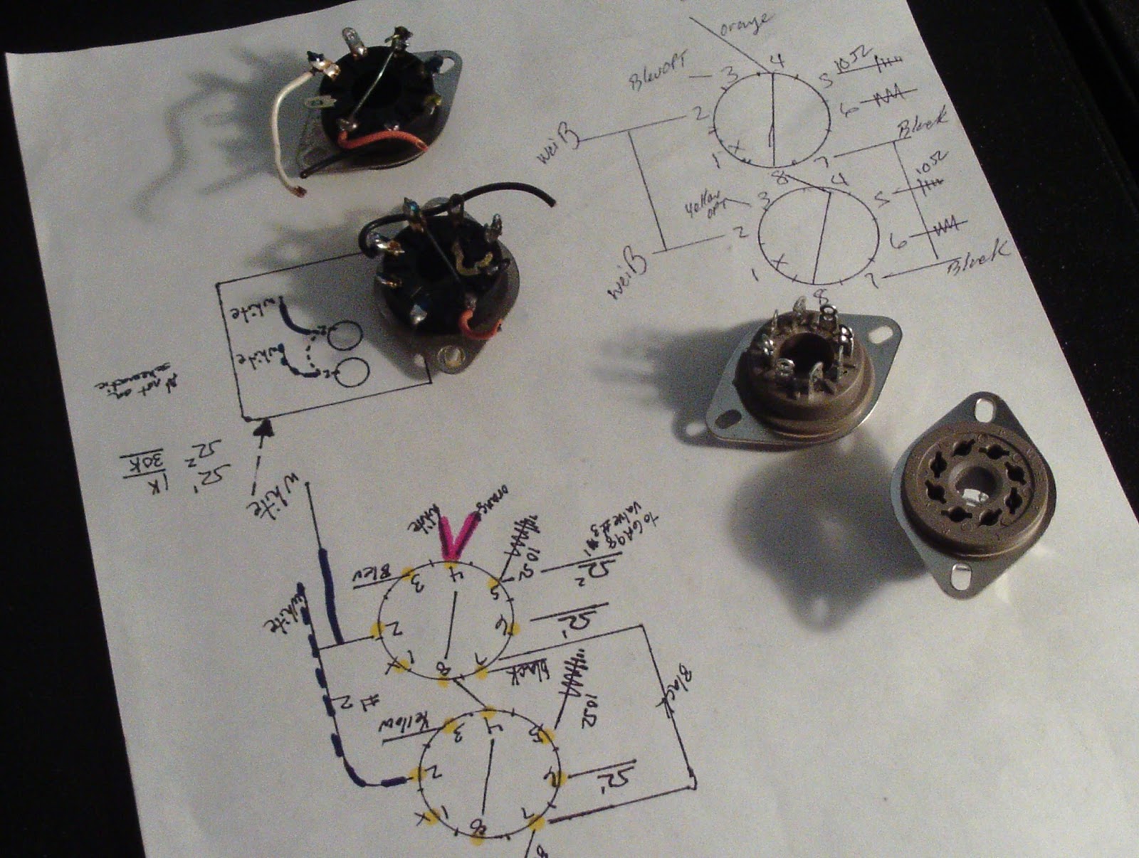
An interesting thing to note on the 1000A series are the variants of the bias circuits implemented. Several biasing configuration are out there using a series of one, two or four bias potentiometers to bias a pair of individual sockets.  Both of these comprise of the independent pot design, which is better as we can dial in each specific tube. As I highlight in our past 1000A posts its important to add a 1/4W 10 ohm resistor from the cathode (pin 5)  to ground of each 7591 valve, this gives you an added protection of destroying the resistor first shunting the tube and a stabile bias parameter. using our bias formula and the 7591 dissipation factor were looking at about 32mA each cathode or 325mV across the resistor (325/10) 32.5mA

Dual Potentiometers

Quad Potentiometers 


Present in the 1000A are tons of oil-type electrolytic capacitors which are well known to be failure prone if not actively failing at this point in their life due to the inferior construction of axial oil-type of the period. All the 1microfarad and larger values were replaced with quality Nichicon TVX axial capacitors up to the 250V+ rating components. Electrolytic in the bias stage were replaced with 630V polypropylene Solens and accompanied resistors replaced. 1microfarad and smaller oil-type were replaced with high quality Panasonic ECW polypropylene film capacitors from .00047 to .1MFD. 


form fitting new axials


Nichicon were used for the filter cap replacements on top and stuffed cans with 40mm diameter. The 40mm 220/220V capacitors had their respective SW-05 diodes updated to 1.5/700V UF4007 diodes in parallel with a .0051 film capacitor along with the isolated SW-05. 

 SW-05 Updated


New 8-pin octal sockets were install for all four 7591 power tubes. The rear RCA’s connectors with buffed along with the OPTs removed and chassis buffed at specific points as shown, the end result was phenomenal, almost mirror like!


Before

After


Buffed RCA Inputs


 I was incredibly impressed with the end result, with the bias dialed in on matched 7591’s and the oil-type removed the 1000A will continue to be as reliable as can be with plenty of power, very smooth yet deep sounding. 

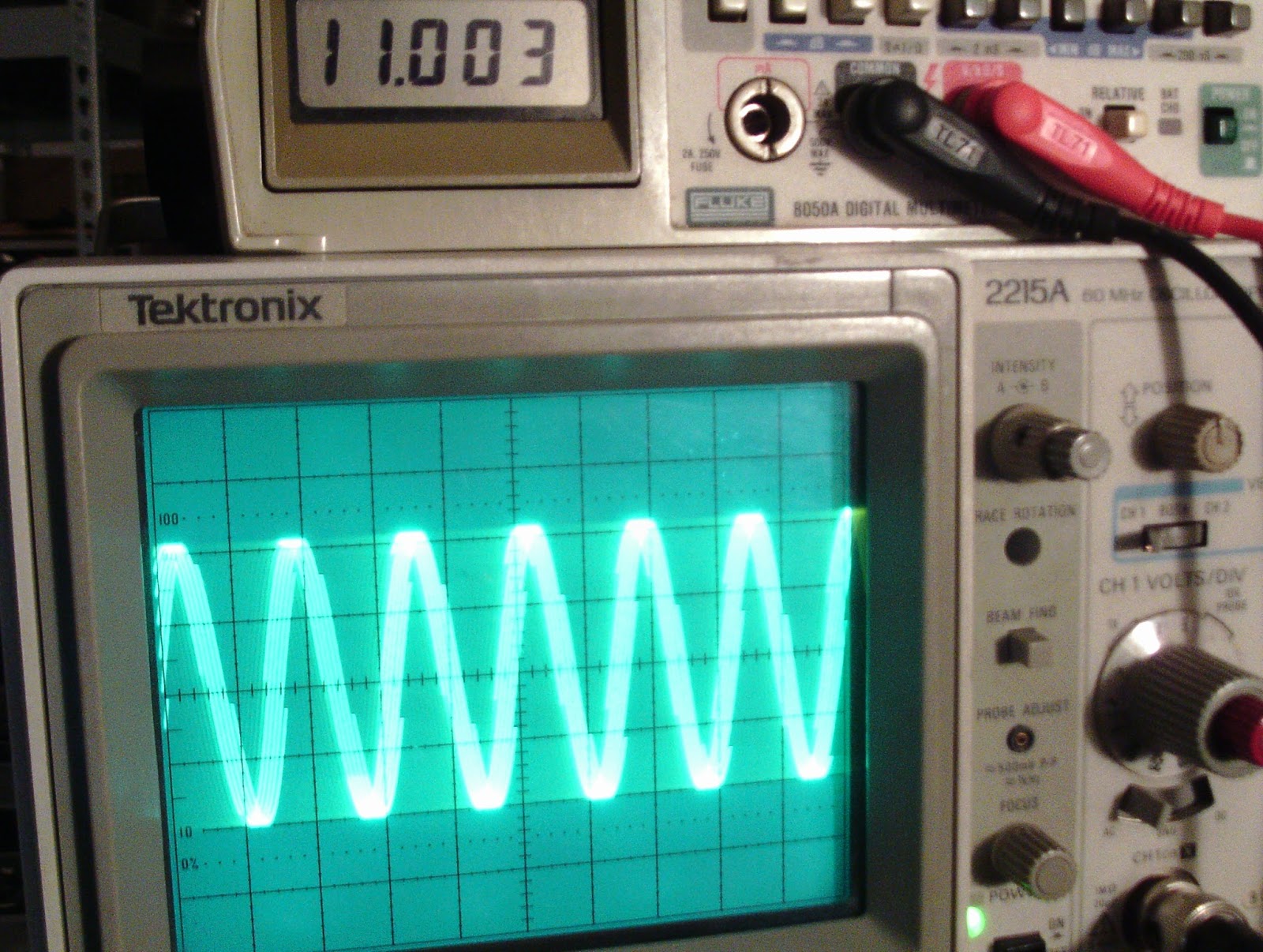
Our Test Station @ Hallo-Fi

Audio Notizen (results) 

Pin cathode bias beim 10Ohm final*
ein 322
zwei 325
drei 325
vier 325

10Khz beim 8Ohm
Recht
3.13V 1.12W (30dB)
4.98V 3.10W (34dB)
10.17V 12.92W (41dB)
16.57 34.32W (45dB)

Links
3.36 1.41W (31dB)
5.20 6.36W (38dB)
9.0 10.12W (40dB)
16.26 33.04W  (45dB)


5.20 (6.36W) (38dB)


9.0 (10.12W) (40dB)


16.26 (33.04W)  (45dB)


Saturday, December 19, 2015

Great American Sound (GAS) Grandson Amplifier

Great American Sound (GAS) Grandson Amplifier 


Got in something relatively new today to me; a GAS Grandson amplifier! This happens to be the meter-less variant of the series, which I happen to prefer. Upon arrival the customer noted one channel was out which was later determined and outlined below.   The GAS Grandson has some impressive specs, rated at a stabile 2 ohm load even at a full sweep! The only real issue is obtaining information on this unit, it took quite some time to work everything out, even with a schematic simply due to a lack of technical data available. 


Driver Assembly
A major theory of operation I want to highlight is the completely symmetric push-pull DC coupled driver stage, as I mentioned before this is a very clean, simple design which I think goes hand in hand with the idea of true reproduction, or fidelity, pure, simple and clean with no BS attenuations.

Before


After


Servo Modificiation
This is a modification that can be performed in regards to bias-servo stage. It used a proprietary GAS100A IC which is really a re-branded MPQ6001 IC I discovered after some research. the MPQ6001 is basically two BJTs in a single package, this can be replaced with two darlington MPSA type BJT’s and removing the IC socket.  If possible I always prefer not to use sockets, i prefer a real metallurgical connection vs a physical connection in most cases. When we talk about op-amp rolling and so fourth then a DIP socket it great, but oddly enough GAS used a IC socket for the TO-92 differential pairs, thats  BS cut corner design, especially for differentials! So the differential IC in this case was removed entirely…pft…


All the elektrolytisch were replaced with Nichicon KA audio grade and Nichicon PW low impedance type for higher voltages. The differential pairs were updated to matched Hfe 1845/992 BJT’s vs the original MPS8099/8599 TO-92s. The 2nd stage BJT’s were updated to MJE15XXX series, I want to add here, the initial failure occurred from a damaged MPSU57 PNP BJT, two legs had broken off the body and were resting in place. Fairly typical as some of the MPS type had thin fragile legs.  The 3rd stage BJT’s were updated to more robust TIP41/42 devices and the heatsink trimmed and re-attached. General diodes were renewed with 1N4148 type and the large 30 ohm 2W and 2.7 1W updated with heavy film/MOX type. Bias re-adjusted for about 50mA which is (.44).50 + for 22mV (id write this down, imagine the fun I had determining this) 

Bias Notizen
beim emitterwiderstand R114/R115 fur 25mV
(.44)0.50


One additional point to make while your updating the IC is to swap out the old bias open-frame type potentiometer, the open-frame especially gunk up and lose tracking easily, we used a bourns precision  1K pot.


Another option to purse is to upgrade the dual Bi-polar FET op-amp IC301, your unit may contain a 1458 or 1558 OP originally I think designed by TI for a general purpose application.  The AD and BurrBrowns variant are a low noise/distortion dual FET application vs a general BP type. In this case we went with a high end (BurrBrown)TI2604 OPAMP along with a new gold 8pin DIP socket for future rolling if desired. 


The filter caps were increased to 12,000 microfarads vs the original 10K, I happen to snag a last few of the Panasonic THA’s for this :)


Man are these amplifiers cool, and luckily, I have two, one for me! Ill be playing around with some OPAMP rolling and trying out some input/output styles so keep an eye out for updates on this one. 


Wednesday, December 9, 2015

Kenwood KA-5002 Major Repair!

Kenwood KA-5002 Integrated Amplifier


Here we have a little Kenwood KA-5002 Integrated Amplifier.  The KA-5002 gets a lot of high remarks from Kenwood-Trio fans out there. Rated at a modest 30W/8Ohm (48W/4Ohm) @ .5% THD (20Hz-20Khz). The KA5002 is a classic direct coupled designed with total symmetrical complimentary driver stages. It also includes a useful RIAA impedance selector and uber low level phono input and balance NULL features for zeroing. 


This unit came in , in a sort of state, an audiokarma member had attempted a restoration. This is why very important to do your research and practice technical skills…or better yet, hire a professional to save a large repair bill. 

This unit would not come out of protection nor would it bias or adjust dc deviation correctly. Faults had been narrowed down to the driver + stages so Ill jump right to the drivers. Another issue we came across after initial repairs during a bench test was the unit would trip its protection at exactly 753mV output. 
I should note an updated bulletin denotes that 3X driver PCB configurations are prevalent on the KA-5002 and they are NOT interchangeable as they include a separate protection assembly or assimilated one. This is SB#2006 INCL ( Before S/N 240001, from 240001 and from 43001)


The following describes (From 430001 PCB # X07-1020-00)
The first item notated was improperly cross-referenced Bipolar Transistors. Final stage 2SA/SC497s should be replaced with TO-126 1220/2690 PNP NPN type, also noted were the dual differential pairs 2SA493 which work great with KSA992 standard small signal NPN BJT's. I suspect from over current in the final stage during the customers operating stage damaged ensured to the VRe2 bias potentiometer, all of which in this unit were replaced with heavy body type.  Also noted were leaky 2SC627 TO-39 type NPN's, which I thought odd. A new correct 100/50 capacitor was replaced as well. After initial biasing test and output we later found that 4.7 ohm resistors had been installed versus 0.47 ohm 3W resistors. New emitterwiderstand were installed and bias compensated (.33x2).30mA(19mV Bias)


As noted on the SB2006, this driver incorporates the protection as well (Qe13-18). Diodes D2-4 were updated to 1N4004 type rectifiers which are damn near impossible to blow. It was noted that 2SC983's (Qe13-15) was  improperly cross-referenced and changed to 1845 BJT's. Qe16 was updated to a modern TO-220 vs the original TO-39 package with a MJE350. An entire diode network of 1S1555 to 18K doesn't exists on the update SB2006 on this pcb but is present. There is also discussion on the 10D-1 Diode and discrepancy between data sheets, I believe its a (1.5)2-2.5A 600V diode at minimal, in some applications the 400# family diodes may suffice. Also noted were missing R48/49 from the restoration attempted, these were replaced with carbon film 1/4W 680 ohms.


The relay was noted to be wired incorrectly shunting the DC to the coil contacts on the same relay sides which was re-wired correctly and a LY installed. The 2,200 microfarard filters were increased to 4700 microfarad Super-T' (Gold) Nichicons and all adjustments remade and confirmed, an update 3A/600V diode to the 1000MFD was replaced.


 Below are some final output rating for a stress test with precision 4.25 loads. As you can see were about 1% within dBm

500mV 1Khz Sine beim 4.25 LOAD

Links
4.80mV 5.42W (37dB)
7.02mV 7.02W (40dB)
10.38mV 25.35W (44dB)

Recht
5.02mV 5.92W (37dB)
7.40mV 7.40W (41dB)

11.00mV 28.47W (44dB)