Tuesday, June 28, 2016

Marantz 1060 Integrated Amplifier 


Today we are showcasing a Marantz 1060 Integrated Amplifier.  The Marantz 1060 is by far one of the most well regarded Integrated Amplifiers of the period, highly sought and prized for its simple, yet extremely mellow, smooth sonic qualities.  Sharing a similar topography of the pre-amp and a simplified 35V regulated power supply to the Receiver variant the 2230.  Paired with something like the Marantz Imperial 6 speaker system and a nice turn table or line source and you have yourself a classic slice of Americana’ Hi-Fi! On this particular rebuild we laid an emphasis on polypropylene upgrades within the coupling/input points.


Power Supply P900
The regulated power supply consists of a simple BJT regulator and filtering network for the 35V RIAA and 27V line level circuits.  After depopulating the assembly its important to carefully remove as much of the glue debris as possible, replacing and cleaning any effected components.  


After cleaning of the PCB is done, all of the electrolytic were replaced with a high temp (105C) Panasonic FC capacitor’s. The original ceramic .01 bypass caps were replaced with a 630V .01 Panasonic ECW polypropylene and the tied 1S- type diodes replaced with a Ultra Fast UF 400# type diode. The regulating BJT 2SC1213 was replaced with a 2383 BJT.


The remaining AC filter 4700MFD capacitors was replaced with a low ESR Nichicon up to a 10,000MFD value and coupling 3000MFD capacitors replaced with two low ESR Nichicon 6800MFD capacitors for an improved bottom end and better rectification filtering.  For hardware sakes we replaced the original switch at this time as well as then tend to gum up and arch resulting in failure.  A new DPDT 7A 250V power switch with a X1Y2 Vishay safety capacitor was installed and fixed to the chassis. 


Pre-Amplifier P400
As mentioned the 1060,2230, 2245 and 2270 all share a very similar topography.  On this assembly we updated all of the NPN small signal transistors of the (GR) grouping 2SC1000 devices to a compliment of new KSC1845 transistors.

The input and output coupling films of .22 and .47MFD electrolytic and mylars were upgraded to a high grade MKP polypropylene film capacitors.  Remaining electrolytic were replaced with audio grade Nichicon KA/ Fine Gold capacitors. The coupled BiPolars were replaced with a 1MFD high grade Panasonic ECW polypropylene film capacitor. 


 In front of this assembly is the tied tone control network, which I advise pulling now to properly clean the tone and volume/balance selector potentiometers and switching. 


RIAA P900
The Marantz 1060 has an infamous phono stage, with a very linear and responsive curve and large compliment of polypropylene the RIAA has one of the best sonically designed, NPN gain staged  phono stages out there in my honest opinion.

As with many of the integrated and 22XX series Marantz, the 1060 utilizes the 2SC458 which is a notoriously bad transistor, known for noise potentials.  Small signal transistors 2SC1000 and 2SC458 were updated to 1845 compliments and H905/906 (458) matched to 1%.  The remaining electrolytic were replaced using  all Nichicon KA audio grade capacitors and original .47MFD films to a high grade MKP polypropylene film capacitors.


Drivers P700
 Using a single PCB symmetric topography the 1060 comprises the differential with a single 945 BJT, through pre-drivers and multiple circuit H705-708 and drivers H709-712 to a quasi complimentary pair of outputs.   The .47MFD input electrolytic were replaced with a high grade Panasonic ECW polypropylene film capacitor and output coupling to a 1MFD MKP polypropylene film capacitor.  Remaining electrolytic were replaced with  high temp (105C) low impedance Nichicon PW capacitors.  Both offset and bias potentiometers were replaced with precision bourns trimmers as well.  Both SVT thermal diodes and TO-3 devices were pulled and new thermal compound applied.  Bias was calibrated at 15mV VS SM detail. 


Audio Notizen


Sunday, June 26, 2016

Sansui 2000A Receiver

Sansui 2000A Receiver


Today we have a Sansui 2000A receiver to showcase.  The 2000 and 2000A/2000X are very similar models besides PCB topography, plus or minus pre amp isolation jumpers and BJT populations. Rated at a modest 35W and manufactured in 1969 this is the last of the early 2XXX series receivers. 

Rectification F1197 Ripple Filter F1195 & Aux PCB’s
The rectification/filtering and block assemblies are all located under the chassis on separate assemblies.  The F1197 had all the electrolytic replaced with a high temp (105C) long life Panasonic FR capacitors and the D003/-4 diodes replaced with Ultra-Fast 400# type diodes along with the D007 @ F1195 and remaining electrolytic.   F1220/1254 had a low impedance PW installed and two .47MFD high grade Panasonic ECW polypropylenes. 


 A new Chassis mount PW high temp (105C) was installed and increased to a 22000MFD/100V capacitor was installed in the mounting bracket  on the top of the chassis. Along with the 3X 2200/MFD 75V capacitors updated with Nichicons to 4700MFD capacitors.


AF Tone F1212 & RIAA F1235
The Tone amp is a single PCB with the multi-tone functions shared. One major issue of the 2000X series is the integration of 2SC458 transistors.  This model only had them within the driver stages but I recommend replacing them if on board. In this case due to the operating frequency the common ksc1845 has a low frequency cut off if substituted.  While this assembly is out we clean all the phenolic based rotary potentiometers and plastic switching assemblies and lubricate. 


The electrolytic on this assembly were updated to audio grade Nichicon KA Fine/Gold FG’s. and low impedance PW’s.  the films at c717/702 were updated to high grade polypropylene MKP’s


The following transistor details is applicable to the F1235 if installed, this unit used a 871 type which is more than fine.  As above the electrolytics were replaced with audio grade  Nichicon KA/FG and low impedance PW’s.  The original  .01MFD mylar’s were upgraded to a high grade Panasonic ECW polypropylene film capacitor.


Driver Stage  F1180
The driver stage is comprised of a PP quasi complimentary output design.  As mentioned earlier the F1180 assembly utilizes the 2SC458 at input transistor TR806/801 which is replaced to a 1% matched KSC1845 transistor.  The input/output coupling films were upgraded to a high grade polypropylene film capacitors (MKP) and remaining electrolytic’s replaced with audio grade Nichicon KA/FG and PW low impedance high temp(105C) capacitors.  Due to the footprint and good tracking the offset(clipping) and bias potentiometers where removed, bathed in D5 and lubricated.  Easier bias notations can be measured at each emitter resistor for a bias of 15mV versus the current draw method.  Also note their are two service bulletins published if intrinsic noise is populated in the circuit.


The integrated Protection indicator is tethered to a output device/input sensitivity 2.5A fusible network in the rear of chassis


RF Sections
The remaining RF stages were all repopulated using a high temp (105C) low impedance PW and stacked Panasonic ECQ film capacitors (1>MFD) and the tuning capacitor shaft cleaned and debris’d.


Buffed RCA Inputs


Audio Notizen


Removed BJT-Caps-Diodes


Thursday, June 23, 2016

Pioneer SX-450 Receiver

Pioneer SX-450 Receiver 


Today we have a nice, smaller Pioneer SX-450 to showcase.  The SX-450 was billed as the entry level 15W stereo receiver in the mid 70’s from Pioneer. Akin to the SX550 in topography with its single PCB PS/driver population. The SX450 is a personal favorite, yes the output is relatively low but sonically these lower wattage Pioneers sound as good as lower watt Marantz 22XX series. Very clean presentation.

Power Supply
As is noted with the SX lower wattage series they utilize single PCB population in their construction.  On this model all of the electrolytics were removed and replaced with a high temp (105C) long life
 Panasonic FC and low impedance, high temp (105C) Nichicon PW variant.  Pioneer used glue on the large vertically mounted 220MFD< capacitors, this glue was treated with lab grade anhydrous and cleaned off the PCB.  The current limiting resistor tent to bake their solder pads here so copious reflowing was necessary throughout the assembly.


The regulating BJT 2SD313 was replaced with a heavy duty MJ 15032 BJT and thermally coupled with compound again to a standalone heatsink, the tied WZ-140 diodes was updated and Q301 2SC1384 replaced with a 2690 BJ-transistor.  I do need to highlight a major discrepancy within the manual;  
SM ERROR** schematic indicates cathode of D304(WZ-140) to Base Q302 (2SD313). PCB layout indicates Emitter Q302 to anode of D304


Driver - AF Stages  - RIAA
The driver and AF stages share a single PCB with the PS circuit.  The pre-amp is integrated into a simplified tone control circuit.  The original films of .1MFD were all upgraded to a Panasonic ECW polypropylene film capacitors.   Within the power stage all of the electrolytic were replaced with low impedance Nichicon PW and audio grade Nichicon KA capacitors.  The input/coupling .47MFD films were all replaced with a high grade Panasonic ECW polypropylene film capacitors.   


The SX450 driver state is a output-capacitor-less design with a differential PNP gain stage.  The differential pair transistor Q201-204 were updated from 2SA725 transistors to 1% matched 992(bf) transistors. The final order output devices which are comprised of a quasi complimentary  of 2SD313 TO-220 transistors were all removed. New MICA and thermal compound was applied along with X4 all new  MJ15029  output transistors which are much more reliable and heavy duty TO packages. 


RF Stage
The remaining AM/FM RF stage which is housed in a single PCB along with the 3 gang variable tuning capacitor.  The Pioneer PLL (phase-locked loop) integration helps support linear and stabile tracking with modest signal pickup.  The remaining tantalum and electrolytic capacitors were updated to low impedance long life Nichicon PW capacitors.  All remaining .47-.1 tantalums were replaced with long life, low impedance Nichicon KL capacitors.


Power Switches on SX-450/550 Units
As outlined in the link below on a SX-550 we had in recently  the SX450/550 is a piggybacked Speaker Selector/Power Switch assembly.  These power switches use a low quality metal straping to conduct, these switches become heavily carbonized from arching AC line voltage upon power up and fed to the AC lamping as flickering and sizzling (ac arching.)  The best and really only solution to these switches is to truly bypass them.  Cleaning will will not suffice, it will hold temporarily but will arch after repeated use.  As photo'd a DPDt 7A power switch should be installed discretely with a properly rated UL X1Y2 safety capacitor.  I have installed several of these in this fashion and it turned out great, the switch is moved to above the serial plate where its not noticed on the rear and the AC line braided.


http://marantzhallo-fi.blogspot.com/2016/04/pioneer-sx-550-receiver-highlight.html

Audio Notizen


Monday, June 20, 2016

Marantz 250 Power Amplifier Rebuild

Marantz 250 Power Amplifier 


Today we are show casing a rare Marantz 250 Power Amplifier.  Originally manufactured in several Mark variants and the 250M and produced from 1971 to 1976 with optional case and rack mounts.  The major differences in the MK variants is the driver topography and rectification assembly.

Power Supply/Protection Assembly
The regulated power supply share a assembly with the protection circuit. Comprised of a full wave rectification path the AC 86.5V is rectified to a stable 58.5 driver rail voltage and filter through two 20,000MFD filter capacitors. Each of the capacitors was replaced with a high grade Nippon 22,000/100V filter capacitor with new bleeder resistors.  The remaining inlet is and secondaries feed a AC rail for the camping.


All of the original Axial electrolytic were replaced with Nichicon TVX (85C) capacitors and both CR rectification diodes to Ultra-Fast UF400X type diodes.   The original TO-69 type MOTO transistor was replaced with a more reliable MJE TO-220 type transistor. 


The integrated protection is a two fold, AC in rush protector upon start up and DC deviation detection circuit peak at 4.5Vdc (-/+ present at the outputs where as the output section is tied directly to the 24V relay wipers.  The original relays due to their open frame nature present many problems in the 240/250 designs.   A new low noise Omron MY2 24V was installed, significant modifications need to be done prior to relay as the coil and wiper contacts are reversed. As photo’d below you can see each coil lead was de-solder and buckled to the wiper, a very very delicate procedure!


Meter Assembly
Output from the driver sections is driven to the meter assembly to Q403 small signal transistor, protected by two small value diodes. buckled to Q404 driver, pushed a bridge rectification network that supplies the DC rails for the meter operation.  All of the capacitors were updated to a low impedance high reliability Nichon PW and zeners updated. Several of the 1/4W resistors had drifted and were replaced with carbon film KOA type.  Often times these meters will become sticky with age due to the original lubricant,  these meters were no exception and still are "reliable" at bests, the 250 is synonyms with issues, even rebuilt.


Driver Assemblies
The driver pcbs is a classic push-pull topography using parked NPN/PNP TO-3 outputs Moto SJ2520/2519 pairs.  The initial stage is comprised on a NPN/PNP compliment in a Sziklai design.  The output is then coupled to the thermally coupled differential transistor pairs Q501/502.  The gain current is driven tot he pre-drivers Q507/508 TO-69 transistors and applied to driver compliment Q510/11.


The differential pair transistors were replaced with thermally coupled performance oriented ZTK795 transistors to stabilize the DC offset and thermally coupled together.  Pre-Drivers were updated to a 1220/2690 compliment TO-220 to replace the MOTO to-69 transistors and drivers to a modified TO-220 mount MJE components.  The bias Q521 was updated to a ztx transistors, due to the solid construction the potentiometers were pulled and deeply cleaned and lubricated on this model.   All of the original axial were replaced with a audio grade Nichicon KA capacitors an MPK and input 1MFD film capacitors along with a high end WIMA polypropylene film capacitor.  


Audio Notizen


Wednesday, June 15, 2016

Sansui G-22000 Pure Power Stereo Receiver

Sansui G-22000 Pure Power Stereo Receiver


I wanted to showcase a very special and somewhat rare Sansui restoration we’ve recently completed, a Sansui G-22000 Pure Power Stereo Receiver! Hailed, along with the G-33000 as one of the biggest receivers ever produced by Sansui.


The G-22000/33 were built with performance and versatility in mind, presenting with an impressive dynamic range of 0Hz-300,000Kz super sonic frequencies.  Using a DC or „Direct Coupled“ amplifier stage and proprietary „Diamond Differential DC circuit,“ the G22000/33 revolved around the capacitor-less topography concepts. Cosmetically designed to be the pinnacle of class and performance with grated noir look, the G-22000/33 are some of the best receivers ever produced in our opinion.


Power Supplies  F2902/F2903  & F2891

The G-22000 utilizes three different independent power supply circuits and three different power transformers.  The Front End (Pre-Tune reference)  with its own power supply network that is tethered as a protective/ Power cycle trigger via a patented umbilical cable.  Each of the driver stages involved its own high quality Toroidal Power Transformers with its own protect/power supply circuit, also coupled to a pair of 15,000MFD filter capacitors for a combine smoothing stage of 60,000MFD. The four filter capacitors were replaced with high quality Nippon Chem-Con 22,000MFD 100V capacitors for a total of 88,000 MicroFarads!


Each independent protection circuits use a rule of 4 detection paths including;  OverCurrent Detection,  Speaker Terminal Short Circuit Protection, Thermal Detection Relay Active and finally a DC Detection Protector circuit.    


Each 2902/2903 contain X2 relays as part of the 4way detection.  All the relays were replaced with new Low Noise Omron LY-2 (24V) relays.  Electrolytic’s were replaced with all Panasonic high temp (105C) FC capacitors and high temp, low impedance (105C) Nichicon PW capacitors.  The Power Supply assemblies contain a large number of 2473/10D1 type diodes which were all replaced with Ultra-Fast UF4005 and standard 4148 diodes.  Remaining MV12 glass pack diodes were replaced with 4148 type in series configuration.  Small Signal and Driver transistors were replaced, updating TR01/4  MJE15032/33 On Semi devices.  NPN 2071 and PNP 939 with MJE340/350 TO-220 transistors.


One of the most important issues to address with Sansui are the Fusible type resistors.   R1-40 selective were all replaced with flame proof Carbon Film 1/2W resistors.  Its very important to notate, on the G22000/33 their is a large inrush limiter resistor for the soft start relays,  when damage occurs or excessive current draw within the unit it can, and likely will stress and slew this large 25W resistor.  In this case some shop had replace the R701 with a 2.2OHM 25W  which had actually skewed its value to an impressive 11.9K OHMS causing the soft start delay to malfunction.  Each of the G2H-21XX soft start relay’s were disassembled and the contacts and spring cleaned.  


Driver Assemblies F2900/F2901

The G-22000 Driver assemblies  each contain a dual FET input differential circuit comprised of a 6leg JFET 2Sk129.  The second stage used the proprietary Diamond Differential designed by Susumu Takahashi and Tadaaki Chikashige of Sansui Electronic Co., LTD Tokyo first publish patent Aug 25th 1977.  The Diamond circuit is designed for a a-b balanced signal via congruently phased signals.  The 3rd order stage is made of a mirror-current and Push-Pull drive design. to a tie  NPN/PNP darlington-Push Pull configuration. (G33000 total PP W/ 8 TO-3 Outputs) The TO-3 output sections were removed and inspected and cleaned thoroughly with noted SIL pads installed.


All of the large 220MFD capacitors were replaced with a low impedance Nichicon PW capacitor, Differential couplings were updated with Nichicon KA audio grade capacitors and FG audio grade and Polypropylene WIMA’s films for the remained.  The coupled .47MFD films were upgraded to MKP polypropylene film capacitors and as above in the PS the MV type Glass pack MV-103 diodes to series (x3) 4148 type standards.   The DC/ Bias potentiometers were updated to precision Bourns trimmers and the remaining Fusible type resistors replaced with 1/2W carbon film KOA resistors. 


All of the small signal transistors were replaced short of the JFET.  2071/939 type small signal transistors were updated to pairs of MJE340/350 type and the 3rd drivers with MJE15032/33 On Semi TO-220 heavy duty transistors with new thermal compound applied.  The remaining 872/1775 transistors were matched to 1% replaced with KSA992/KSC1845 type. 


AF STAGES F2890/F2899 Flat Amp-Tone 

The Tone amp and Flat amp stages comprise a single symmetric PCB and F-2899 as two separate symmetric assemblies mounted via connectors to the underside of the chassis.  


On the F2890 assembly all of the electrolytic were replaced with audio grade Nichicon KA BiPolar VP Nichicons.  The coupled films were replaced with .1MFD high grade WIMA polypropylene film capacitors.  The small signal TO-92 872 transistors were replaced with 992 type and the TO-220 2071 with MJE340 type.


F2899 symmetric assemblies involve again the 2SK129 differential JFET nun gain stage with an apparent significant slew rate.   Like the above Af assemblies Nichicon audio grade KA and FG were installed along with the .22MFD coupling film to a MKP high grade polypropylene film capacitor.  The remaining 2473 diodes were replaced with standard 4148 type and 872 compliments to 992 type TO-92 transistors.


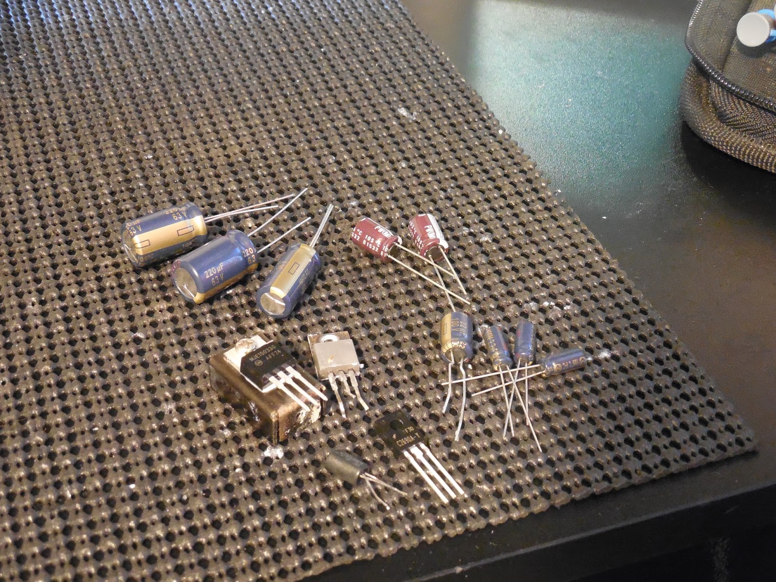
A few miscellaneous items to cover such as installing new power cords 


and a shot of all the 250+ components replaced over the 25 hours it took to rebuild and tests;


Audio Notizen


EQ STAGES  F2880/F2884  RIAA/Motherboard

The EQ (Phono) stage is touted with a again a 2Sk131 Dual JFET bootstrapping current array following a non gain stage and ending with SEPP (single-ended Push Pull) stage.

Like the above AF assemblies the electrolytic were replaced with a audio grade Nichicon KA. The large 5MFD coupling film was replaced with a high grade MKP polypropylene film capacitor.  The remaining 2473 updated with standard 4148 diode and the 872 small signal transistors updated to 992 type.  


The F2884 Motherboard assembly had both large electrolytic replaced with low impedance, high temp (105C) Nichicon PW’s and the coupling films with high grade .47 polypropylene film capacitors


RF Tuner F2920

The G-22000/33 has an incredibly impressive RF stage. With a linear tuning 5-Gang tuning capacitor and Dual MOSFET driver designs allow for solid pick up even in hostile enviroments, with distortion limiting circuits and Wide/Narrow and advanced Muting/Noise filters this is one of the better RF sections I’ve seen. We replaced all of the tantalum and electrolytic with low impedance, high temp varaint (105C) Nichicon PW capacitors and Bipolar Vp capacitors. .1MFD BP was replaced with a Panasonic ECQ film capacitor. The tuning capacitor was dusted, cleaned and the points shaft location contacts cleaned. 


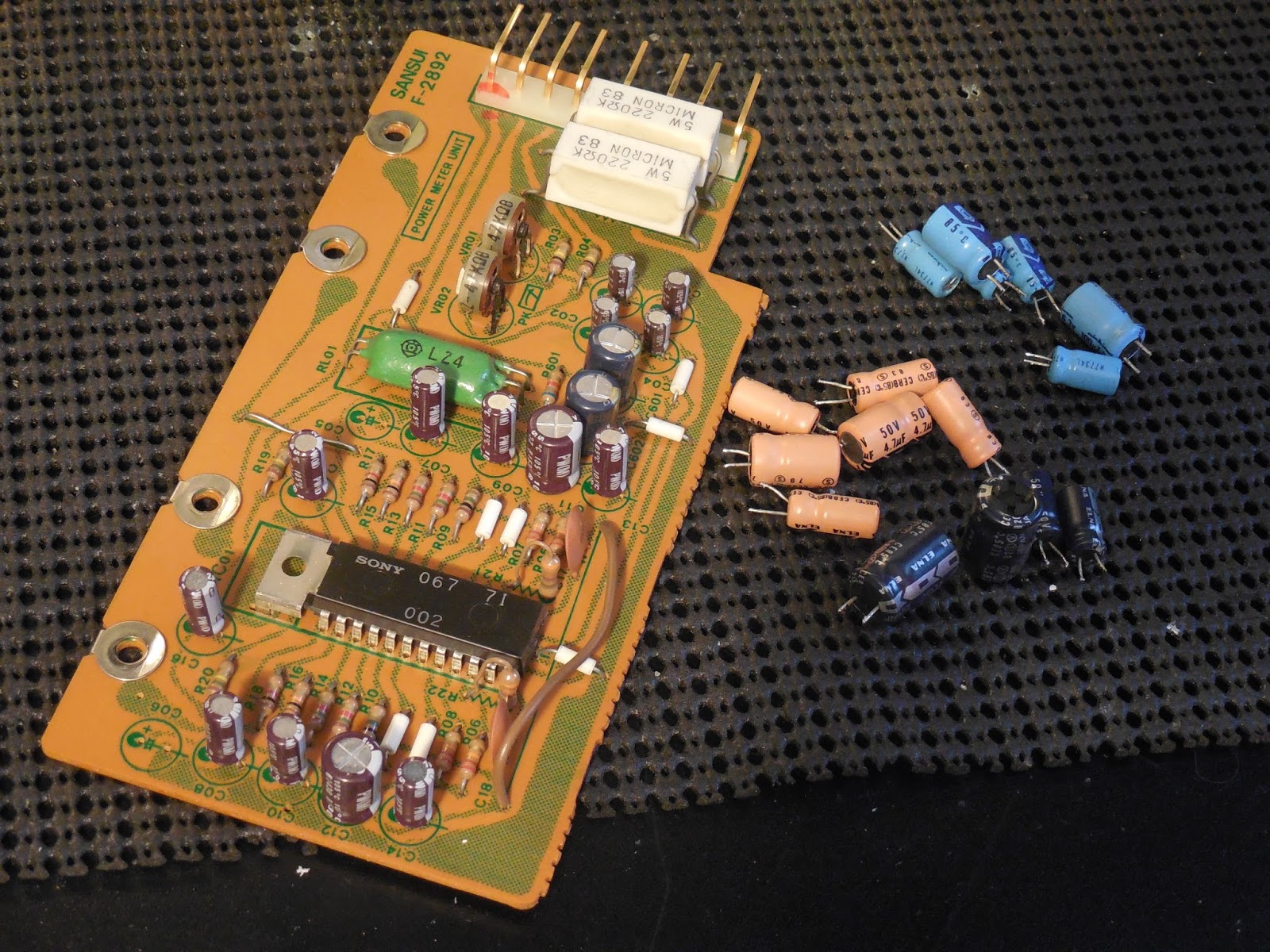
Meter & Volume Assembly Assemblies F2886/F2892

Remaining Stages as F2886 Volume/Mic Amp PCB’s had the remaining electrolytic with audio grade Nichicon FG and low impedance Nichicon PW’s.  The volume potentiometer on the G-22000 is an impressive calibrated 4 Gang 32- stepped attenuator!


Along with the F2892 Peak Meter assembly with Nichicon PW capacitors.  Sansui express these as professional series outer magnet Meters responsive from .1-600 Watts Pkv


F2885 Mic First Amp PCB was repopulated with high grade WIMA polypropylene film capacitors and a single audio grade Nichicon KA along with a updated KSA992 small signal transistor. The 


F2906 output circuit PCB with a updated 10D1 to UF4005 diode and two high grade WIMA polypropylene film capacitors.


As each stage was removed all the contacts and switches were deeply flushed, cleaned and then lubricated. Including the fan assembly with a light touch of 3:1 and thoroughly cleaned of dust and potential matter and cleaned with lab grade anhydrous alcohol. Some shop before had replace for some unknown reason the Front End unit AC Cord with a Polar AC cord....the G-22000 Driver section has a BiPolar AC receptacle installed in the chassis so why someone did that is beyond me. The replaced cord was removed and a UL grade BiPolar cord installed…


Audio Notizen
As we can see the performance parameters of the G-22000 is damn impressive!