
CA-1010 Yamaha

CA-2010 Yamaha

Here we have two Yamaha CA Integrated Series amplifiers. The CA1010 and CA2010 are both similar models with a few distinct differences.
For starters the CA2010 utilizes all enclosed and some stepped ALPS potentiometers. The other is the control IC for the metered circuits. Another differences is an increase to 22,000 microfarad filter capacitors vs 18KMFD in the 1010 amongst other class A and A/B integrations for stability including all matched FET's.
Power Supply & Protection PCB’s
For both the CA1010 und 2010 they are almost identical designs for the Power Supply,protections circuit other than the slight difference in lamp rails. For all the electrolytic’s we replaced with high temp (105C) Nichicon PW and Panasonic FC capacitors. Diodes updated to UF type general diodes. New Omron LY relays were installed as well as at the filter cap PCB. The power supply on each also use a pair of 10 and 2.2MFD bi-polars which were replaced with Nichicon EP which come in available 105C temperature variances. I want to note its important to remove the component glue thats used on the 1000MFD/330/220MFD capacitors.

CA1010

CA2010

Pre-Amplifier/ Tone Control
Again very similar topographies used in both the 1010 and 2010 models. As noted one of the biggest differences is the use of enclosed stepped potentiometers for the tone and enclosed pots for the Volume and Balance controls. The few electrolytic’s populated here were replaced with audio grade Nichicon KA capacitors. Both PCB’s incorporate a lot of low Mylar film values, In my experience with the CR series swapping these out with polypropylenes didn’t lend the best results. We did try the .56KMFD with a PP type but resorted back to the Mylar films in this case.

CA1010

CA2010

Function/RIAA, Coupler & Meter PCB Assemblies
The difference in the tone/RIAA centre is the replacement of IC103/4 with yamaha IC #; MC#00164, in a matched FET, DIP package than the 2010 models. Some models also contain a difference at D101/102 diodes and should replaced the VD1212 glass pack with a 4148 in series respectively. The CA2010 also introduces the front end 3.3MFD and 1MFD electrolytic’s. The lower value 1MFD were replaced with PP type WIMA film capacitors and all others with low impedance Nichicon PW or audio grade Nichicon KA front and back. The series of 220/33MFD tantalum capacitors were all replaced and upgraded to audio grade Nichicon KA/PW low impedance electrolytic capacitors in both CA1010 and 2010.

CA1010


CA2010

Meter PCB’s NA06836 and CA1010 both had all the electrolytics replaced with low impedance high temp (105C) Nichicon PW capacitors. The 2010 uses a integrated PM-02 IC where as the 1010 uses a series of BJT circuits for control. The ca2010 lacks the shielding the BJTs need on the 1010 models.
CA2010

Also dont forget the coupler PCB on the rear chassis, two axial should be replaced with with modern Nichicon TVX, as I noted in other rebuilds the quality of axial's from this time period is questionable.

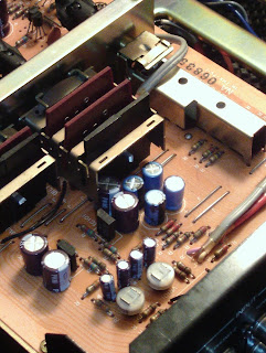
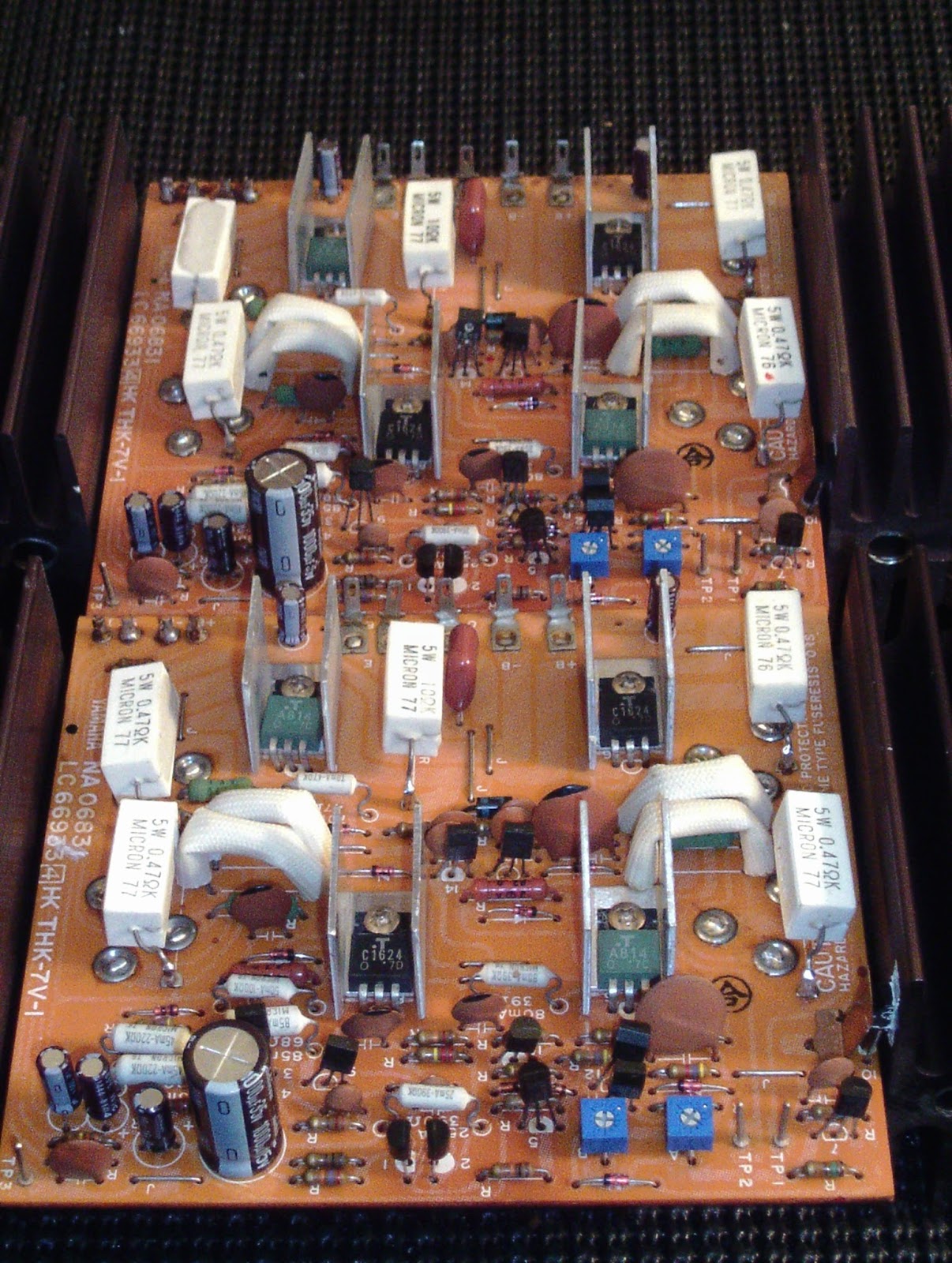
Drivers
The neat thing about the CA 1010/2010 is the Class A/ B operation feature. Unlike later models that incorporate micro-switching i would advise to never “Hot-Switch” the features, the Class A operation has a significant higher operating parameter as well at about 138-148 Fahrenheit Vs around 100F in A/B. (complied averages: multiple users)
CA1010
All the electrolytics on the 1010 were replaced with high temp (105C) low impedance Nichicon PW’s, the original film was replaced with a high quality polypropylene Panasonic ECW film capacitors. Its important to update again the glass pack VD1212 at D301 with 4148 in series. First stage differentials were replaced with matched 992 BJT’s and 2nd tier TR303/304 with matched 2383YBU BJT’s. The original 2.2K ClassA/B potentiometers were replaced with 2.2K 1/2W Bourns precision trimmers. Because of the dual operations their are two bias points.
Audio Notizen CA1010
punkten beim TP1 und TP2 fur A/B 25mV
punkten beim TP1 und TP2 for A 280mV


CA2010
Again, electrolytic here were replaced with high temp, low impedance Nichicon PW’s and films replaced with polypropylene Panasonic ECW’s films. their are no VD glass pack diodes to address on this assembly. The CA2010 differs by using a dual FET differential IC rather than matched BJT compliments. We did however upgrade the 3rd stage driver compliments to modern On Semi MJE15030/31 TO-220 transistors replacing the 2sc16234/2sa814 compliments. The 2010 also utilizes a mid-bias point potentiometer which directly correlates to mid stage drive so setting this will greatly affect your bias and output points. All the original 2.2K potentiometers were again replaced with precision Bourns potentiometers.
Audio Notizen CA2010
Audio Notizen CA2010
punkten beim TP1 und TP2 fur A/B 25mV
punkten beim TP1 und TP3 fur 0V
punkten beim TP1 und TP2 fur A 300mV

A different approach I took after comparing fusistors. In the 1010 we have hear all are well with 2% tolerance still, yet on the 2010 most seemed to be drifting about 5% high. Its very important to do your math when converting fusistors to metal films or the like as we did here. The fusistors in this stage short excessive consumption after a failed BJT device, thus shunting and protection the distal operating circuit from the failure point. We want the same characteristics now but in a more reliable resistors such as films. so we take IxR =V V/R .
IE:
FR301/302 (4.7/230mA) 4.7ohm 1/4W (4.47 und 4.35) (.2486 W dissipation)
FR303 (100/50mA) 100ohm 1/4W (100.91) (.25 W dissipation)
FR304 (68/85mA) 68ohm 1/2W (68) (.4913)
FR305 (390/25mA) 390ohm 1/4W (393) (.2873 W dissipation)
FR306 (47/70mA) 47ohm 1/4W (47) (.2303 W dissipation)
Both CA1010 and 2010 filter capacitors were replaced with low ripple Cornell 22,000 microfarad 100V capacitors and fitted. The final step included converting both circuits to Dc rectified LED illumination. The 14V rails for the lamp assembly needed to be adjusted at the voltage divider so a 180 Ohm 3W resistor was installed with a 1A/100PIV diode in line and 1000MFD filter capacitor for smoothing giving us a correct operating voltage for X5 3.65Fvd White LEDs at 100mA draw. (thanks Joe on the Math)
CA1010

CA2010

3.5V 20ma LED adapted festoons
LED Conversion notizen fur CA2010
14.8Vac W/ 1A/100PIV diode w/ 1000MFD capacitor @ 19.8Vdc
para: 3.5Fvd 20mA
19.8Vdc - 16.3Vdc working
16.3Vdc / (.020x5) = 163 Ohm V/I=R
16.3Vdc x 0.1 = 1.63W (3W min)
PCB mid-modification procedure; notate inrush R and filter (C)


Hi Noah,
ReplyDeleteI have a functional 2010. Wondering about sound and stability improvements after this type of restoration. What is the approx. Cost excluding shipping?
Thanks