Thursday, December 29, 2016

Jim's Yamaha M-80 M-85 and C-85 Restorations

Yamaha M-80 & M-85 Power Amplifier & Yamaha C-85 Pre-Amplifier 


The Yamaha M-80 and M-85 produced during the latter/mid 1980’s (84-86) were part of the top tier M-Series Amplifiers each with a matching pre stage. The M-80 and M-85 exhibit very close characteristics/design and output with the M-85 adapting the known service bulletins applied to the M-80 versions for stability and performance.  The performance parameters of theses amplifiers continue to impress with a rated output of 250/W @ .003% distortion and capable of driving 2-ohm loads and a incredibly accurate wide-range LED peak power indicator circuit. Both units involve a Class-A operation which is highly recommended NOT TO USE due to severe overheating issues.


Yamaha M-80 & Yamaha M-85
This M-80/M-85 pair came in with some issues. The M-85 needed new binding post and the chassis straighten due to damage and the M-80 had several blown output devices and notable failure. The speaker binding posts on these amplifiers is relatively easy to upgrade and frankly a must, the original plastic mounts becomes very brittle due to the heat of the unit and will often crack and break. New Relays (MS4U/G4W 24V & JC2aD 24V) were installed and the lead wire/post for the c+ banks removed and hard-wired for safety/longevity.


On the M-80 we had extensive cascade damage noted with; X3 open emitter resistors, x2 open 2.2OHM output tied resistors and one 2.2 skewed to 10Ohms. Three of the four output devices were blown, bias serve transistors, two 7.5V diodes and a handful of resistor arrays.  The M-80 does require significant work before regular operation to install important service bulletin #665 (03/15/1986) to protect further damage in the power supply and output stage (cascade failure prevention..too late on this model :( )  In addition many of the amplifiers are probably improperly biased due to an error in the SM indicated a bias over two of the compliment device emitter resistors incorrectly. 

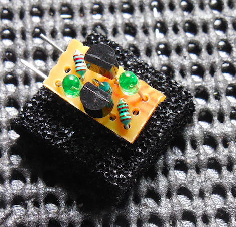
Another serious notation is both amplifiers used original 1000MFD/100V filter capacitor with a large amount of glue used for vertical orientation. This glue at this point HAS damaged basically any associated components…completely eating away at the metal of resistors/diodes and the copper busses. Its important not too forget the electrolytic for the front LED wide-band display as well which had new low impedance PW’s installed.


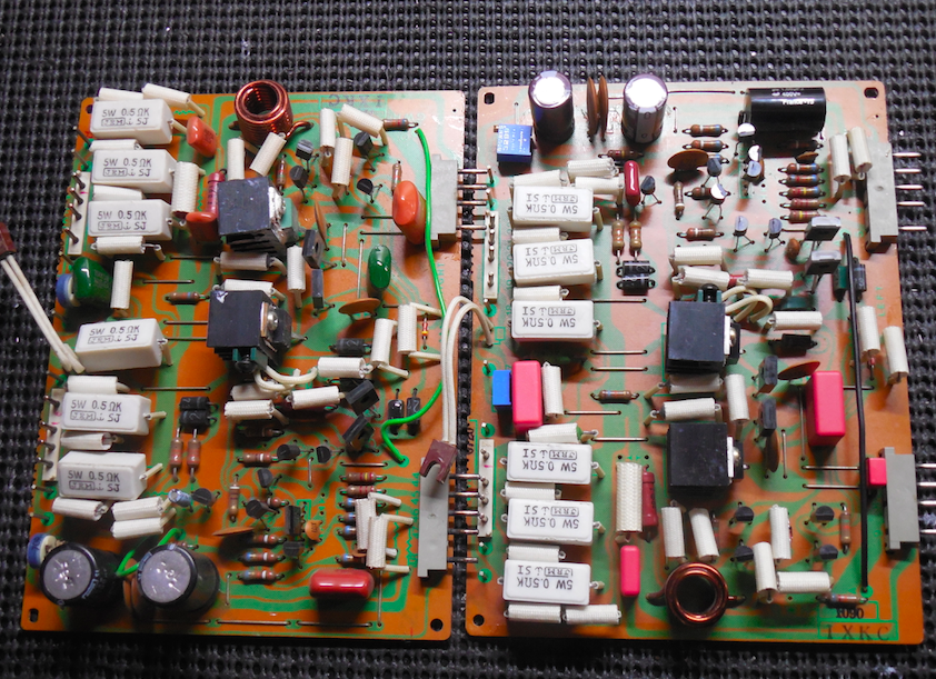
MAIN PCB (PS/DRIVER) * PS PCB
All of the electrolytic on the Main-PCB of the M-80/85 were replaced with high temp (105C) Nichicon PW capacitors with an increase in operating voltages including the large 1000MFD/100V with high grade WIMA polypropylene film capacitors (.01/001/450V). A SM/Schematic error indicators  a 100MFD polar capacitor but should be a 47MFD BP, this was replaced with a Nichicon VP 47MFD BiPolar capacitor.  Both 1K potentiometers were replaced with precision 1Kohm Bourns trimmers.


The differentials stage consists of a dual JFET 2Sk389 device and a NPN stage, the differentials were replaced with modern low noise Fairchild TO-92 devices matched within 1% including constant current, Vbias and pre-driver and driver stage transistors updated (1381/3503 devices with a 47 ohm resistor tied to each collector (TO-126 devices) plastic tabbed TO-220-3 Toshiba type 4793/1837 driver devices were upgraded/installed as well. New 1/2 W KOA metal film resistors and .22/5W wire-wound emitter resistor installed.


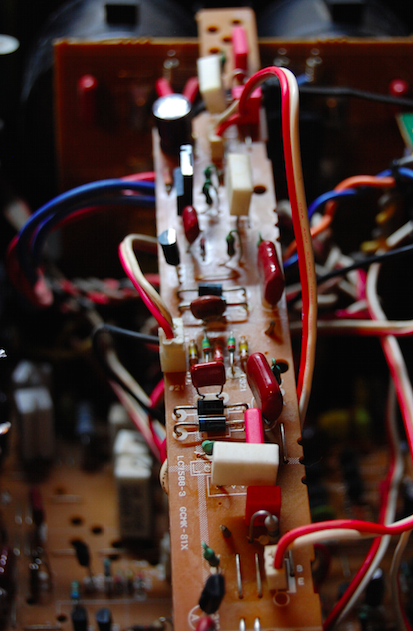
The additional PCB is mounted to the heatsink’s in long narrow PCB strips with the other compliment of Sanken devices, the regulator BJT’s replaced with plastic tabbed Toshiba 1837/4793 installed and new TO-92L fairchild devices for better heat dissipation, new 100MFD low impedance Nichicon PW electrolytic and WIMA polypropylene film capacitors installed as well. 


AUDIO NOTIZEN

YAMAHA M-80 


YAMAHA M-85


Yamaha C-85 Pre-Amplifier 


The matching pre-amplifier to the M-85 Power Amplifier, the C-85 is an incredibly well built pre-amplifier. With exception power supplies and filtering, quality original components plus a 4-gang enclosed volume potentiometers (the balance is installed very weird) and a parametric EQ control!


The C-85 uses a large amount of IC gain stages (1st order Tone Control; BA4581S) where as the second tier 6dB Flat amp uses a Dual JFET 2SK389 differential stage as the above M-80/85’s do to BA4561 IC’s.


Dual PS
All of the electrolytics within the two power supply networks were replaced with low impedance long life Nichicon PW capacitors with an increase in operating voltages. The two TO-220 heatsink mounted regulators 2SD1275/SB949 were exhibited large amounts of radiant heat damage to the PCB and surrounding area, these were upgrade to modern heavy duty MJE TO-220 devices with new thermal compound.


RIAA EQ/PARA AF & AF Stages
The AF stages had all electrolytics replaced with audio grade Nichicon KT and Fine Gold (FG) capacitors along with high grade WIMA polypropylene film capacitors and ECW film capacitors. All of the large 22MFD BP capacitors were replaced with Nichicon VP BiPolar capacitors. The remaining 2S1555 diodes upgraded to modern 4148 type and the driver stage 2SB650/438 TO-92 devices upgraded to modern  Fairchild TO-126 2690/1220 devices


AUDIO NOTIZEN


Monday, December 19, 2016

Greg's Pioneer SX-1980 Monster Receiver Restore

Pioneer SX-1980 von Receiver-Aus-Gangsleistung


Today were featuring a special monster receiver…the Pioneer SX-1980!  The SX-1980 was introduced in the late 1978 to compete with the 2600/2500 Marantz, Sansui G22-33K and Kenwood KR9600 monster receivers with an original costs of $1250USD.


The SX-1980 featured some incredibly factory specs and was is a total behemoth weighing at 78lbs! The SX-1980 shares some very distinct features with its kin and like the SX-1250 touts a massive toroidal transformer and four 22,000/100V filter capacitors. Restored to this degree these receivers can still easily fetch 3500-5500$USD…


Power Supply und Protection AWR-154

The power supply on the Pioneer SX-1980 leaves a lot to be desired sadly. The original design suffers from inherent overheating issues and a failure prone JFET 2SK34 devices. A lot of the thermal issues can be addressed using better thermal transfer material like Sil pads with better thermal compound and more robust BJTs and 105C rated capacitors. 

BEFORE


AFTER


The large toroidal uses separated windings for each defendant channel! These are supplied to their own bridge rectifiers and a pair of 22,000MFD filter capacitors. The separate voltage driver stage, pre and RF sectional have a dedicated full-wave rectification network and regulating devices as well as a DC supplied lamp rails..convenient…

The protection consist on a auto inrush limiter during power phases and output /overload protection and significant DC deviation. A PA3004 IC triggers these responses on the power supply.


The first and foremost important item to tackle is the removal and upgrade of the original 2SK34 JFEt devices used to initiate the 80V supplies and provide a 2.2mA current source. I want to take a second and recognize the work of EchoWars & MarktheFixer’s work here in detailing a protocol and trial and error for this modification, only minor differences have been installed but the base is his design.  

The modification is comprised of a pnp/npn diode drop network using an array of 1.2K emitter resistors a 1M (current feed BJT) using two sub mini 1.9V green LED’s such as; The 2SK34 zener protect network is then removed from this assembly as its unused. 
 ((1.9Vfd-.6Vfd)/1200ohms X2 for a 2.166mA current source.


The electrolytic capacitors were replaced with high temp (105C) long life Nichicon PW capacitors with an increase in operating voltages. New coupling MKP polypropylene films were installed for the rectification stage. The three large axial capacitors were replaced with TVX Nichicons with an increase in operating voltages. Research will show that often the 35V zener fail or are damaged as well, these were replaced with two diode in series to a 500mW diode.  Several resistors exhibited scorch marks or were entirely blown open, these were all replaced with 1/2W metal film KOA resistors. R102 was removed and a lead ran to the 330MFD axial capacitor to accommodate the new 24V relay without damaging it.  Both relays were updated to LYS and MY2 24/48V low noise Omron relays. 


The large regulator TO-220 devices were all replaced with  On-Semi heavier duty TO-220 MJE devices with SIL TO-220 inserts to help dissipation including the both heatsink mounted 2SD325s to MJE devices. All other transistors were replaced as well, upgraded to TO-92L and TO-126 devices with modern low noise, more robust equivalents.


Power Amplifier Recht und Links GWH-109


The initial driver stage is comprised on a single package 2SA979 to a cascade array with a constant current controller (Miller Effect circuit,) The 2SA979 was replaced with two modern low noise Fairchild PNP devices with a 1% matched Beta range with a shared emitter, all associated above BJT’s were replaced with low noise modern /FairchildOn-Semi TO-92 and TO-126 devices. The pre-drivers and associated network were all upgraded to modern low noise Fairchild TO-126 (KSA1381/3503) devices. Both drivers were upgraded to heavy duty, robust On-Semi TO-220 MJE devices with new thermal compound.  Both 150K/100 bias/offset pots were updated to precision Bourns trimmers and 1S2473 diodes to modern 4148 type. 

BEFORE/AFTER


The electrolytic were replaced with high temp (105C) low impedance Nichicon PW 100Volt capacitors. the .22MFD and all remaining films were replaced with audio grade high end WIMA and MKP polypropylene film capacitors. The original bat-winged outputs were removed and new thermal compound applied with MICA pads. 


The output meters read a logarithmic .01-540W scale without the need for calibration range using a logarithmic Compression circuit for the peak indicator feature. The .47/220MFD were all updated to low impedance, high temp (105C) Nichicon PW capacitors and ECW PP films. I did note the initial meters were off calibration.


AF Circuits: Flat Amp AWG-058 und Tone Control AWG-059 W/ AWM-119

The AF circuit int he SX-1980 is very close to the SX-1250 when we compare the designs, where as the RIAA EQ stage greatly differs with a flat amp (22.5dB Gain stage)

The flat amp is built on an initial dual PNP device like the driver PCB using a 2SA979 device which was replaced with a 1% matched BETA low noise Fairchild TO-92’s with a shared emitter. The remaining gain stage comprises a low impedance SEPP output, all of the transistors were updated to modern low noise Fairchild TO-92 and TO-126 devices.  

BEFORE


AFTER

The electrolytic capacitors were replaced with a low impedance Nichicon PW and audio grades Nichicon KT audio grade electroltics with an increase in operating voltages. The coupling capacitors were replaced with high grade MKP polypropylene film capacitors.


The input is then fed to the AWG-059 tone control stage which does feature a bypass defeat option. The SX-1980 uses a main and sub-line attenuator circuits for the baseline twin controls and a sub-sonic hi pass control. 

BEFORE


AFTER


The compliments of 2SC1312 transistors were all replaced with a low noise Fairchild TO-92 devices. Electrolytic’s here were all replaced with low impedance Nichicon PW and audio grade KT capacitors and two 10MFD Fine Gold  Nichicon’s with an increase in operating voltages. 


Filter Amp
The Filter amp is a-12dB octave NFB active filter circuit with RC passive filters. As above AF stage the electrolytics were upgraded to KT and Fine Gold audio grades and a low impedance filter PW capacitors. New low noise Fairchild TO-92 devices were installed.


EQ RIAA AWF-030

The SX-1980 houses one of the better RIAA gain stages I’ve seen yet with two handy adjustments of the input resistance (all tested at 47K(50K) standard) and input capacitance.

The initial gain stage of the AWF-030 is a 2Sk131 JFET which was a ultra-linear dual device and a NPN differential stage which was updated to two 1% matched Beta low noise Fairchild TO-92 devices. The constant current and voltage stage were all updated to new low noise Fairchild TO-126 and TO-92 devices with the driver SEPP stage to new heavy duty KSA/KSC 940/2073 TO-220 devices.

The electrolytic 2200MFD filters were updated to Nichicon Fine Gold audio capacitors with the remaining replaced with low impedance Nichicon PW and audio grade KTs capacitors.


RF Stage / Filters und MISC.
The 22Kmfd filter capacitors were all replaced with new Nippon Chem-Con 22,000MFD 100Volt capacitors with new capacitors mounts to adapt better to modern available dimensions and future placement.  


The X4 bulbs were replaced with multi-facet SMD LED’s for long life use.


RF Stage
The front end /RF  tuner is one of the best designs out there in these receivers, as Pioneer often has. With extremely low noise qualifications (M-50dB/St-30dB) and a unique automatic pilot canceling circuit to suppress multi-plex noise and maintaining separation and responses output. 
The remaining RF stage capacitors were replaced to low noise, high temp (105C) Nichicon PWs and we tried new Vishay tantalum capacitors.


AUDIO NOTIZEN