Pioneer SA-9800 (HG) Integrated Amplifier

Im very excited to present this restoration. Here we have Pioneer’s TOTL Integrated Amplifier the SA-9800. This model is the HG 220/240V 50/60Hz European model that came in all the way from the United Kingdom (UK.) The following reports in this writeup are detailed at 220V/50Hz.

The SA-9800 was considered in 1979 Pioneers best of the best within the SA series. Touting the image factor, the Ringer-Emitter (RET) output stages and their proprietary Vari-Bias circuit colludes to a NLA non-switching amplifier design creating some distortion factors at an impressive .002 % dB THD+N factor after the rebuild!

To operate such a model quite the investment is required to operate a 50Hz 240V unit here in the states, without the proper test equipment over saturation, oscillations, voltage damages can all occur. A customer of ours in a engineer who custom built this setup for Hallo-Fi Electronics. We use a 2500W/Ch Carvin PA amplifier in junction with a massive step transformer and a custom built micro-controller setup for variable voltage and a selectable 50/60Hz cycle operations. These are not cheap so most shops do not invest in such equipment, but due to the large number of european units we get in each year it was a must, especially for our German customers!

Power Supply AWR-194
One of the biggest issues with the SA-9800 is the heat generated from its Class A topology and its constant current-ON design. Pioneer also used a poor BJT choice for the PS regulating BJT’s and current limiting resistor values, which bakes the supply assembly and often leads to significant damage. This particular SA9800 came in with a blown up power supply..several resistors and BJT’s were damaged with one TO-92 actually blowing apart its silicon frame!
Because of the notate damage and heat issues the entire power supply assembly was replaced short of the inductor and x4 resistors!
BEFORE

AFTER

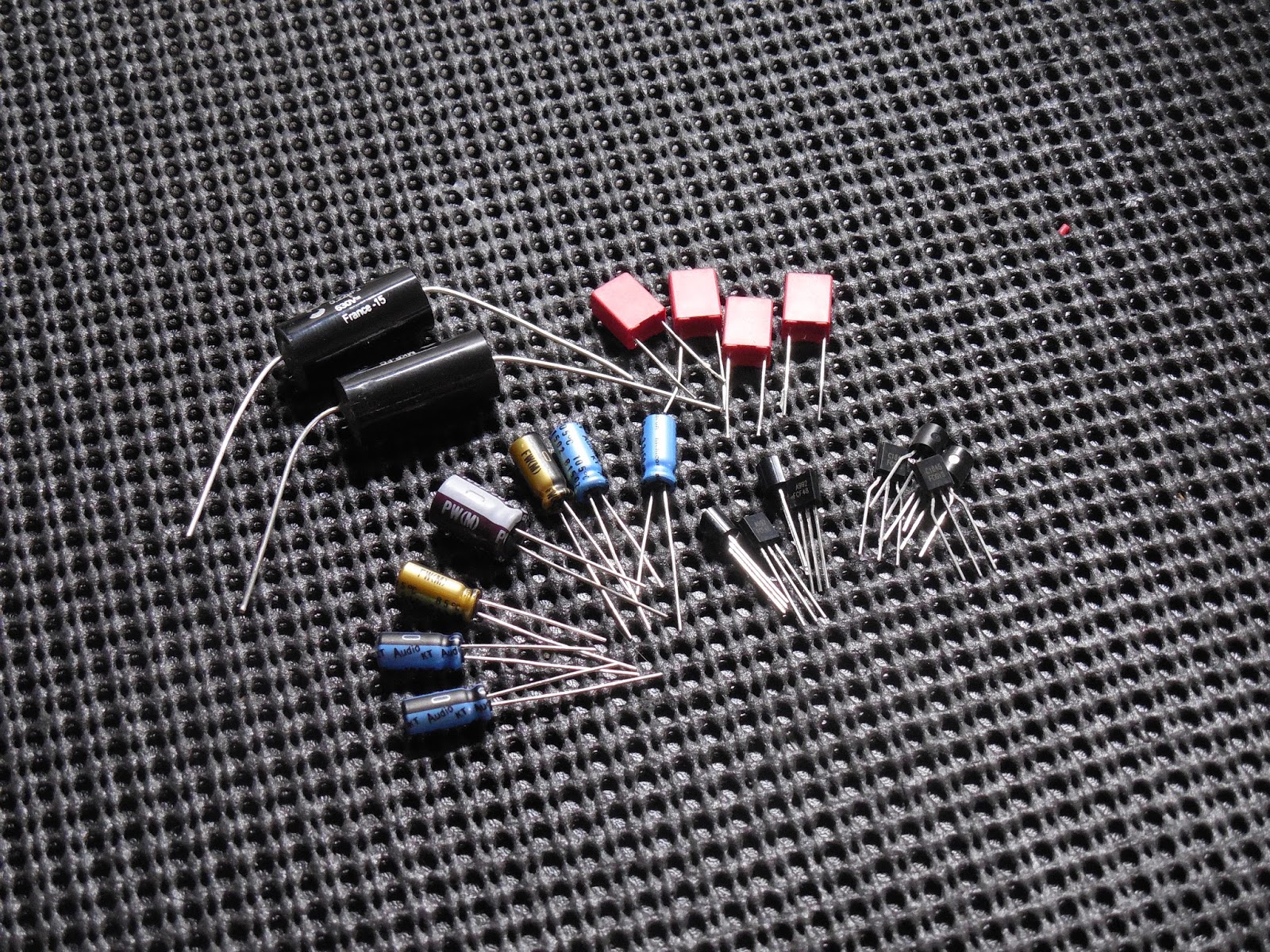
All four regulating TO-220 BJT’s were replaced with modern On-Semi TO-220 devices with a much higher current/voltage capacity and new thick viscous thermal compound to facilitate in thermal transfer between the heatsinks. As you can see from the before photo someone had attempted so half ass repairs on this PCB in the past using very poor transistor cross references, damaging tracing etc..

These were all replaced with new TO-126 and TO-92L modern low noise transistors with a higher current/voltage specs. The TO-126 and 92L BJT form factors help with better dissipation. Along with all new BJT’s all but X4 resistors were replacing which include the limiting resistors. Several were replaced with 1/2W and flameproof applications. In addition all new diodes with the rectification stage were used with increased current handling capabilities and new 4148 general diodes.

A new bypass ECW polypropylene film and new Vishay X1Y2 safety capacitors installed in this stage as well. Both 220MFD axial were replaced with TVX Nichicon’s and high temp (105C) low impedance Nichicon PW electrolytic installed with an increased voltage rating.

Rectification Assembly AWR-192
The main filter caps are positioned on the AWR rectification assembly. An overhaul of this stage consisted of upgrading the bypass films with WIMA polypropylene .01/630V as well as all X8 3A SR3AM-4 rectification diodes to a more robust 3A 600V rectification diodes. The X4 15,000MFD 71V filter capacitors were replaced with high grade Nippon capacitors with an increase of operating voltage and working capacity to 18,000MFD 80V capacitors for a better lower end response and filtering.


And for the final modernization a new LED indicator diode :)

Protection AWM-163
The protection circuit in the SA-9800 has two main features; to protect against transient and inrush limits during a power cycle operation and DC deviation detection at the output stage.

A new low noise Omron MY2 48V relay was installed to replace the original, I find the Omron low noise type more heavier duty, more costly but beefier relay with a protect indicator.
Several of the 1S type diodes were replaced with general 4148 type as well. The three electrolytic were replaced with a high temp (105C) low impedance Nichicon PW capacitors. Each BJT was updated to modern transistors with an increase in voltage/current handling with TO-126 and TO-92L packages choose for better dissipation.

Indicator AWV-002
The SA-9800 is known for its use of a Fluorescent Indicator tube (FL) which uses thermionic output from a cathode against the separate anode segments of the package which produces a light. The AWV circuit is known to fail often on these I think due to the limited of the DIM function limiting the differential drive circuits which consists of two HA12010 IC’s, one per channel after the “Logic IC TA7318P-A) device.

Electrolytic on this assembly were replaced with high temp (105C) low impedance PW’s with an increase is operating voltage as well as the TA coupling films to high grade 400V ECW polypropylene film capacitors.

AF Stage Tone AWG-124
The pre-amp stage consists of multi-stage tiered dc coupled gain stage configuration. The initial differential gain stage is achieved using a 2SK129(A) JFET device, with the following a 5 pin tied emitter pop differential and control stage.

I am not a fan of the single package dual device single emitter transistors, they tend to generate excessive noise versus a separate package and tend to be less reliable in my opinion in non JFET applications. This was replaced in each channel with 1% matched PNP modern low noise transistors with the output stage NPN device replaced with a modern Fairchild low noise transistor.
Comparison

Electrolytic here were replaced with all audio grade KT and Fine Gold (10MFD) Nichicon capacitors with an increase in operating voltages. The .18 films were all upgrade to a high grade MKP polypropylene film capacitors.


RIAA EQ GWF-116
This is one of the most complex RIAA networks I have ever seen! The RIAA EQ stage in the SA-9800 features several relevant functions for different cartridge types such as a MC and MM input along with a Load factor setting just for MM type cartridges to preset the input capacity and impedance factors!
The RIAA also features a inteference filter…because of the extremely high input sensitivity naturally from the input RIAA stage intrinsic and or RF pickup may occur, this introduces resistors to the input network to inhibit this, though this does attenuate the RIAA deviation plot so I advise against its use for hifi playback. A separate but inline MC stage is used, consisting of a 3 stage tiered dc coupled gain stage for a nominal output gain of 28dB.
**The below compiled RIAA report is the first and only compiled published online to date generated here at Hallo-Fi; I used the standard input factor for most MM carts setups at 100pF and 50K input


The initial differential stage consists of a ultra low noise Jfet 2SK131(S), a NPN differential and constant current stage. Several of the original TO-126 type transistors were seated in BJT stand off’s which allow the device to be inserted rather than soldered, these were removed and new modern Fairchild TP-126 devices installed directly onto the PCB, several of these devices were freely moving in their sockets!

Several diodes were updated to modern 4148 type and the input .01MFd films upgraded to a high grade WIMA polypropylene film capacitor. Remaining electrolytic were replaced with audio grade Nichicon KT and low impedance PW’s of increased operating voltages along with X14 100MFD electrolytic capacitors!

RIAA Curve Deviation

AF Stage Filter GWS-176
The subsonic/hipass filter assembly has several electrolytic capacitors, the 1MFD elecotrlyic were upgraded to audio grade WIMA polypropylene film capacitors and remaining electrolytic to audio grade Nichicon KT type. Both switch were cleaned and lubricated. At this stage all the potentiometers and switches were cleaned using Caig Labs Deoxit concentrate and followed up with Caig lipid based F5 lubricated. Access points were made on the high grade enclosed 22-step volume attenuator which was cleaned and lubricated with the above.

Drivers GWH-129/130 (Euro Designations)
The heart of the SA-9800 NSA (non-switching Amplifier) design which enables a constant On-On operational which eliminates the transient potential of push-pull on/off topologies.
BEFORE

AFTER

A word to the wise, NSA circuits are not for the faint of heart, unless you have a great degree of circuit understanding do not tackle these on, they are unforgiving. The original driver board as seen in the “Before” photo they use a large amount of resistor stand offs, not to eliminate heat as these are only 1/4W resistors but to avoid pcb destruction in the event of failure, they use of correct rated resistors and relying on the circuit protections is more than sufficient and eliminates the potential for intra/infrasonic noise pickup that comes from floating components like they did. These resistors were replaced with 1/4 and 1/2W carbon film KOA resistors.


The electrolytic capacitors were replaced with audio grade KT and low impedance PW’s including the tantalum capacitor with an increase in operating voltage. The two .1 films near the inductor were replaced with high grade MKP polypropylene film capacitor upgrades. Both Bias/offset and fine tune bias trimmers were updated to precision enclosed Bourns potentiometers. New modern Fairchild transistors in a TO-126 and 92L package for better dissipation were installed as well as NOS driver BJT’s. During the rebuild several driver transistors were tried, resolving on the fact that the NSA circuit requires a higher bandwidth operating device of at least 95Mz to obtain its rated distortion factors.

MJL Output Device Upgrade Tests
Another option explored was upgrading the output transistors, based on the ring-emitter output design. The original are thermally coupled to the bottom of Pioneers skipped designed heatsinks. The new devices were On-Semi complementary MJL3281/1302 (A) devices. Both were set at a max idle of 70mV. The original footprint allows for easy mounting of the newer TO-264 package, because of the heat and location I choose to hardware directly to the output device, any plastic connect would over time bake and become brittle and other mounts were too large for my liking.
Testing channels

Both units were under identical load and signal input parameters and were tested with the below results. The original devices were removed and new compliments of MJL devices installed for the final product for a more new reliable, modern selection.
Testing channels

Both units were under identical load and signal input parameters and were tested with the below results. The original devices were removed and new compliments of MJL devices installed for the final product for a more new reliable, modern selection.


MJL Comparison Report


Audio Notizen *Final Report