
Marantz 2130 AM / FM Stereophonic Tuner


The 2130 is considered one of Marantz TOTL tuner’s of the period, with an onboard oscilloscope display, sharing cosmetic similarities with the 2110 style. The 2130 features a 5 gang FM and 3 gang AM variable capacitor, quartz lock and MPX features.

P800 REGULATED POWER SUPPLY & TRANSFORMER NOTATION
The regulated supply is split into two section, a regulated supply for the tuner circuits and a simplified rectified supply for the P900 high voltage scope circuit. The 2130 boast a robust supply with good noise suppression for the front end demands with simplified 1/2 and full wave rectification stages.
All of the small signal devices were replaced with low noise TO-92L Fairchild devices for better dissipation and a new TO-220 OnSemi, modern robust regulator device with new thermal compound applied. New Hex-Fred, ultra-fast soft recovery rectifiers in TO-220 and axial formats installed.

Capacitors were all replaced with low impedance, high temp (105C) Nichicon PW type with an increase in operating voltages and several increased in overall capacity for better filtering including high voltage 350V type.

BEFORE

AFTER


Regulated Supply Confirmation


30Y8ZD Transformer Notations
The 2130/2110 series tuners have a common failure mode developing within the strapped transformer for the scope driver. Often times, I have seen at least three models, exhibit shorted primary windings on the 30Y8ZD taps as noted below. Another failure mode is the voltage selector hardware which for a reason I have not determined yet causes a shorting of the center tap. In this version a hard wired modification was employed to remove the voltage hardware (retained for aesthetics on chassis) and wired for a permanent 120V supply. A new transformer was installed from a donor 2110 parts unit.


Shorted Primary impedance indicator (Top), Proper impedance parameter (Below)


P900 SCOPE AMP & PR00 SCOPE DISPLAY SWITCHES
The P900 was used by Marantz in many series with minor differences such as in the 2500/2600 monster receiver designs. With a Jfet 2SK from end and robust high voltage regulators.
Both sets of TO-220 regulators which i’ve noted with high failure rates were replaced with high voltage capacity modern, robust TO-220 OnSemi devices with new Wakefield synthetic thermal compound and calibrated.


The scope switching assembly capacitors, including tantalum were replaced with a low impedance Nichicon PW and high grade WIMA polypropylene film capacitors.

BEFORE

AFTER


P200 AM & FM IF
The largest PCB for the IF and AM front end handling, worth noting is the separate filter scheme of a narrow (180Kz ceramic) and wide Saw type with LC filter block.
All of the electrolytic capacitors here were replaced with a low impedance type Nichicon PW with an increase in operating voltage. Tantalum and choice ceramics were replaced with a high grade WIMA polypropylene type.
BEFORE

AFTER


P300 MPX STEREO DECODER
The MPX stage is oriented around the Q301 Hitachi 11223 IC with a DIP 4558 output stage.
All of the electrolytic capacitors here were replaced with a low impedance type Nichicon PW with an increase in operating voltage. Tantalum and choice ceramics were replaced with a high grade WIMA polypropylene type.

BEFORE

AFTER


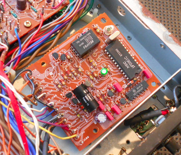
PC50 QUARTZ LOCK
The quartz lock phase employs a DIP (uP)D861C and HD7490 IC’s with a low voltage relay.
The BP capacitor was replaced with a audio grade MUSE Nichicon and low impedance PW Nichicon capacitor for the polar type. A high grade MKP and WIMA polypropylene film capacitors were installed.

BEFORE

AFTER


PT00 BUFFER AMP & MODE SWITCHING
The AM / FM buffer stage utilizes a dual DIP 4558 output stage with integrated filter/gain controls.
All of the electrolytic capacitors here were replaced with a low impedance type Nichicon PW with an increase in operating voltage. Tantalum and choice ceramics were replaced with a high grade WIMA polypropylene type.

BEFORE

AFTER


