Thursday, March 31, 2016

Marantz Model 22 Receiver Duo Rebuilds

Marantz Model 22 Receiver


I wanted to showcase two Marantz Model 22 receivers that came in for restoration. Manufactured from 1969 to a last run of 1972, their are two version, one revised and the early models.  Rated at 40/W over 8 ohms.  The Model 22 is an excellent sounding early Marantz receiver pre-dating the 22XX series runs. The Model 22 tends to be a very extensive rebuild as it hosts an array of the 2SC458 transistors which are very failure and noise prone BJT devices. Along with a plethora of service updates and bulletins. 


P800 Power Supply & P980 Speaker Protection
The Model 22 has an interesting design for the power supply. using a dual configuration supplying a 27/35V rails for the tone/phono and driver + driver stage and a 12V rail tap for the RF and differential front end driver sections. 


The original topography used two large metal 1000/MFD 50V can capacitors which were replaced with a 10mm leaded high temp (105C) low impedance Nichicon PW capacitors. The remaining electrolytics were replaced with high temp (105C) low impedance Nichicon PW and Panasonic FR/FC capacitors. The section bridge rectifier bypass with .01/MFD Panasonic ECW film capacitors. 
The original RF front end H801 BJT 2SD324 was replaced with a 2073NPN BJT. I do want to note that H801 pinout is different on the unrevised and revised versions.  Pinout of this TO-220 is typically BCE. On the unrevised model the pinout is ECB so the TO-220 was mounted under the chassis with a new MICA insulator, this is better than cropping the legs to the correct BCE, just transposed the BJT. Both H803/804 2SC734 BJT’s were replaced with 1845 NPN BJT devices and H805/806 1S332 diodes replaced with a 7.5Vfd diode. Note the output difference for the two model at J805 of 35 and 27Vdc.  The two 4700MFD 50V filtering capacitors were replaced with a low ESR Panasonic THA 5600MFD capacitors with a low profile to help keep the surface down from heat.


P980 
The speaker protection PCB is located under the P800 assembly. Their are two very different topographies used between the two Model 22 versions. The revised version omitted the flyback diode arrays H984/985 for some reason, which is added back with a Utra Fast 4005 diode cathode at J983 and anode to J984.   The problematic 2SC984 metal transistor seen on the later 2270 mods is replaced with a more reliable MJE243 BJT device and H981 2SC828 updated to a 1845 NPN BJT device.  All the electrolytic were replaced with a high temp (105C) low impedance Nichicon PW capacitor.


The older LY relay was mounted under the chassis to a L bracket near the output inductors. I actually havent come across this mount but on these 2# series Marantz, they tack the relay with a screw through the bottom threshold.  I replaced the original my a 24V Low Noise Omron MY2 relay, fixed with a plastic safe epoxy to the bracket.


P700 DC/FM Amplifier Assembly
Again, similar to the P980 assembly their are two versions of the P700 PCB. One with a BJT network and one version consisting of a 4 NPN driver configuration.  All of the electrolytics here were replaced with a audio grade Nichicon KA capacitors and the original .22MFD mylar films replaced with a high quality WIMA polypropylene film capacitor.  The original H705/706 were noted to be the problematic 2SC458 devices, which were replaced with matched 1845 NPN BJT’s along with H707/708 2SA494 with complimentary KSA992 BJT’s. H709 was replaced with a general 4148 diode.


P400 Tone/Pre Amp & P300 RIAA (PHONO)
The pre-amplifier topography reminds me of what we see in the 1030/1060, 2230+ Marantz. A very simple, musical symmetric topography. I love this design. Employees with a NPN front end gain stage and variable RC feedback design.
The original mylar .22MFD input coupling films were replaced with two high quality .22MFD WIMA polypropylene film capacitors. Due to their footprint some mounting modifications had to be integrated.  High grade WIMA polypropylene were also used for the output 1MFD capacitors. All remaining 100/22/2.2MFD electrolytics were replaced with a audio grade Nichicon KA capacitor. The P400 assembly again uses the problematic 2SC458 BJT device at H401/402 which were replaced with 1845 NPN BJT devices. Due to the high rate of issues within the Model 22 pre-amp the remaining BJT’s were updated as well with KSA992/KSC1845 low signal BJT devices. 


P300 RIAA
The phono stage in any Marantz is superb after some TLC, some of the best I know, the documented RIAA response is damn near flat on the Model 22. Impressive stage.
The original 1MFD electrolytics were replaced again with high grade WIMA polypropylene film capacitors and remaining electroyltyics with Nichicon Fine Gold and KA capacitors.  This is one of the few RIAA marantz stages without the 2SC458 or glass pack VD diodes which is nice to see. 


P600 Power Amplifier 
The Model 22 driver section is a push-pull symmetric single pcbs assembly, with the exception of the input its a direct coupled design utilizing a degenerative feedback array. The P600 uses a TO-99 differential amplifier IC for the initial gain stage versus a pair of differential pair TO-92’s thermally coupled. The MC1741 is updated with a LM741 package available in a TO-99 or DIP8 device.


LM741 Block Diagram


Input films at C601/602 were replaced with a high quality Solen MPK film capacitor. All the electroylytics here were replaced with a Nichicon Fine Gold 100MFD capacitor. Signal path mylar’s were removed and replaced with a high grade WIMA polypropylene film capacitor along with the output .22MFD capacitor with a footprint modification at the output pins. 


Bias punkten 
J606/608 for 10mV beim R961
J607/609 fur 10mV beim R962


RF Stage
The remaining AM/FM PCB assemblies had their respective capacitors replaced with a low impedance high temp (105C) Nichicon PW capacitor along with two 220MFD capacitors foil side. The dual AM/FM tuning capacitors were cleaned with 99.999% anhydrous alcohol and dusted. 


LED Lamping
New Led’s were installed at the meters and dial display. These were hand-made using the original BA9S bulb bases. By heating the metal base you can separate the glass bulb and remove the original filaments, leaving just enough room for diode/resistor.
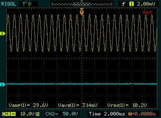


Audio Notizen

Still graphing our response but initial results look great.  
500Hz 19.14Vrms (45.79W/Ch @ .057%dB THD+N
1000Hz 19.14Vrms (45.79W/Ch @ .059%dB THD+N


10000Hz @ .059% THD+N

Still graphing but response is well within spec


Tuesday, March 22, 2016

Sansui G-8700DB Repair Highlight

Sansui G-8700DB


I wanted to take a moment and highlight a Sansui G8700DB we had in recently for repair.


The 8700DB is very similar to the 9700. With two phono inputs, stepped attenuator, 160W/Ch output at .025%dB THD the G-8700DB was a real performer. Typical of the G series with the big dual front knobs and driver topographies.   This unit came in with a totally fried driver section, defective right driver and in protection.  I’ve seen very similar failures in almost all the G-series.


On this unit the resistors array for the bias and 3rd driver had completely burnt up, carbonizing some sections of the PCB and marring the heatsink. Resistors R26-35+ had become either totally open or fused and caught fire.  One of the major issues with fusible resistors. 2nd order BJT’s in the left along with several series R’s were open. I noted at least 25% of the intact fusible resistors were 10-15% off their rated tolerance wheres as carbon films noted along 3-5% tolerances. 


Judging from mis-matched out-put devices, BJT’s and capacitors a repair was attempted at least some point in this units life.  Along with the noted defects above the right channel output devices TO-3  were shorted between emitter and bases along with open emitter resistors. 


On both F-3074 drivers all existing fusible resistors were replaced with 1/2W and 2W MOX(1W<) and carbon film KOA resistors.  The left bank 3115/14 assemblies had their .33 5W emitter resistors replaced and all TO-3 (2SD665/2SB645) replaced with 5% matched MJ15022/23 devices. 


All the electrolytic were replaced with audio grade KA and low impedance PW Nichicons’ C17/18 Ceramics .022 replaced with high grade WIMA polypropylenes, along with the C11 .047 mylar with a high grade WIMA PP film.  Original bias/offset potentiometers replaced with a precision bourns potentiometer. 


New first order differential pair transistors, bias and 2/3order transistors replaced.  BJT counter parts with 2SA939 /2071 MJE350/340 heavy duty devices and driver transistors to MJ15033/32, TR13 1904 with a tabbed KSC3503. New heatsink applied to the missing devices on the left channel. 


I’ve noted several issues with the 939 transistors, along with damage above the F3070/3072 power supply/protect assemblies.  TR02 (939) was replaced again with a MJE350 OnSemi BJT device and its associated D02 (4148)D602 (Ultra-Fast 4005) and R06 due to excessive current draw (Over 65+ initial Offset)


Final output results are well within expected ranges. 170.20 W/Ch @ 8OHM w/ 0.023%dB

100Hz L/R 28.53Vrms  @.0076%dB THD+N


1000Hz L/R 28.53Vrms @ .0075%dB THD+N


10000Hz L/R 28.53Vrms @ .011%dB THD+N


Total Output (continous @ 8OHM)  160WCh @ 8OHM w/ 0.025%dB THD
1000Hz L/R 36.90.30Vrms 170.20 W/Ch @ 8OHM w/ 0.023%dB THD+N Before Clipping plateau. 

1000Hz L/R 38.30Vrms 183.361W/Ch @ 8OHM w/ 0.030%dB THD+N Before Clipping plateau. 


Monday, March 21, 2016

Pioneer SX-850 Receiver

Pioneer SX-850 Receiver 


Here we have a nice Pioneer SX-850 receiver. Produced from 1976 to 1977 it was a mid entry SX series receiver.  Prized for its direct coupled phono section the SX850 also presents an honest .1<% THD noise floor at a very modest 65+ W/CH.  Like many of the SX series, the 850 offers a superb RF section featuring a 4 gang tuning capacitor and FM/AM MOSFET drive/lock.


Power Supply AWR-101
On the power supply PCB were several noted back electrolytic capacitors, many of these smaller SX series exhibit significant radiant heat issues on the 850, mostly due to the fact that its oriented under the chassis, sandwiched by the bottom plate and through natural convection offset of the heatsink mounted BJT devices and current limiting resistors.  The electrolytic were replaced with high temp (105C) long life Panasonic FR/FC and Nichicon low impedance high temp (105C) capacitors. Q7 updated (2690AYS) and several general diodes to UF type. I also recommend reflowing all solder connection on this PCB. 


New high quality Chem-Con 18,000/80V capacitors were used to replace the original 15,000/50V filter capacitors. and a .1MFD high grade ECW polypropylene film used for bypassing removing the original bypass resistor.


Protection AWM-062
Similar to the SX-828 we recently showcased, the 850 has a typical dc deviation detect circuit with a 24V relay.  Such as the relay with the T-Cover the relay was removed and case flushed, a new MY2 was installed.  Electrolytics were replaced with all high temp (105C) capacitors as Panasonic FR/ Nichicon KL hight temps (.22MFD/50V) and PW electrolytic along with the problematic 2SC1384 BJT updated to a 2690AYS device. 


RIAA AWF-011
Again arranged very similar to the SX828, the 850 seated the RIAA assembly under the chassis near the protection assembly. A very clean symmetric design producing a very quite and nice phono stage. The electrolytic were replaced with a low impedance Nichicon PW and audio grade Elna Silmic II capacitors with Q1/2 725 class BJT’s updated to matched 992 devices. 


Power Amplifier PCB AWH-059. 
Extensive work was done on the driver section. Updated all the capacitors, using Nichicon PW high temp (105C) long life and audio grade Nichicon KA /Fine Gold capacitors. for the input 1MFD a high grade WIMA polypropylene film was installed. New precision bourns bias potentiometer and DC cleaned and lubricated. 


The 1st order differential transistors were replaced with 1% Hfe matched ksa992 transistors, while the bias/2nd order 2SA818/1628 devices were updated to KSA1381/3503 BJ-transistors. 3rd order driver pairs were replaced with matched 5% MJE15033/32 transistors for a more heavy duty device and new thermal compound applied.  The TO-3 output devices were pulled and new MICA insulators and thermal compound applied. 
Audio Notizen
punkten beim #12 und 13 fur 20mV (VR3) &  punkten beim #27 und 28 fur 20mV (VR4
DC beim G und punkten 9/10 auch 24/25 fur 0Vdc VR1/2


AF Flat -Amp AWG-038/AWG-039
Removing these sectionals isn’t too bad, this is where totally access to cleaning the switches/ rotary controls is for a proper cleaning.   All the tantalum capacitors were replaced with 1<MFD replaced with audio grade Nichicon KA capacitors and the latter with high grade WIMA PP film capacitors. All others were replaced with audio grade Nichicon KA or low impedance Nichicon PW’s. The switching assembly (AWS-094) 220MFD was replaced with a Nichicon PW type.


RF PCB AWE-071
The remaining RF section was recapped with high temp (105C) low impedance Nichicon PW and Nichicon KL fur .47<MFD capacitors replacing the original tantalum capacitors.


LED Conversions
New globe LED’s and function indicators installed and routed.  The new LED’s present a very brilliant clean white light, opposed to the original Amber. Much cleaner IMHO plus with the added benefit of less radiant heat and overall current draw. 


Audio Notizen (8OHM @ 1.006Khz(.003THD) SINE)


1W/CH @ 8OHM <=.05%dB THD
LINKS (RATED 1W/CH @ 8 OHM <=.05%DB THD)
—2.85VRMS (1.015W) @ 0.018%DB THD+N

RECHT (RATED 1W/CH @ 8 OHM <=.05%DB THD)
—2.83VRMS (1.00W) @ 0.018%DB THD+N


33W/Ch @ 8OHM <= .05%dB THD
LINKS (RATED 33W/Ch @ 8OHM <= .05%dB THD)
—16.15Vrms (32.602W)  @ 0.044%dB THD+N

RECHT (RATED 33W/Ch @ 8OHM <= .05%dB THD)
—16.25Vrms (33.007W)  @ 0.044%dB THD+N


65W/ch Continous PV @ 8OHM <=.1%dB THD
LINKS (65W/ch Continous PV @ 8OHM <=.1%dB THD)
—24.81VRMS (76.942W) @ .051%dB THD+N

RECHT (65W/ch Continous PV @ 8OHM <=.1%dB THD)

—24.50VRMS (75.031W) @ .051%dB THD+N