Wednesday, January 13, 2016

Marantz Monster 2385 Receiver

Marantz 2385 Receiver 


Heres a pretty fairly rare treat we get to showcase. A Marantz 2385 receiver. A monster of a unit, rated factory at 185 watts/CH! The 2385 steps away quite a bit from the earlier 23XX models and is closer related to the 2500 receiver. The 2385 uses such as the 2500 a dual primary massive toroidal transformer in a black housing along with dual section 6800MFD capacitors. Another difference is the separate driver assemblies known on the 2330/2325 but single topography for the 2385/2500. The 2385 also came in a Euro variant with no AC accessory switching or P600 Dolby integration of course. The other major difference is the implementation of a soft start relay on the 2385 vs the 2330/2325.

Opened Chassis


Power Supply P850 
The power supply has a real easy access point clipped above the dual full wave rectification and in front of the filter capacitors.  The large 1000/470 MFD axial were replaced with Nichicon TVX type. The remaining electrolytic replaced with high temp (105C) long life Panasonic FC capacitors.  The Q851 diode which is a standard S1B102 type was replaced with a ultra fast 4005 diode. Both common cathode/common anode TO-220 rectifiers were replaced with modern MUR1620 TO-220 devices. As noted on the PCB some significant heat is generate off the LED 330 voltage dropping resistor, I recommend swapping it as we did with a new one for longer projected life, unlike the other 23XX series, this is a fixed regulated switching supply.

Before


After


PQ00 Soft Start & PN00 Audio Muting 
Separate assemblies exists for the relay and soft start mechanisms. A new PB1467-ND Soft Start was inserted and affixed with matching pinouts.  A new Omron low now MY-2 was installed, note the 2385 needs a 48V dpdt relay. Electrolytics on PN00/PQ00 were replaced with high temp (105C) long life Panasonic FC capacitors and didoes updated to general 4148 type. 


PE00 Tone Control/ Pre amplifier Stage & PT00 Filter Amp PCB’s
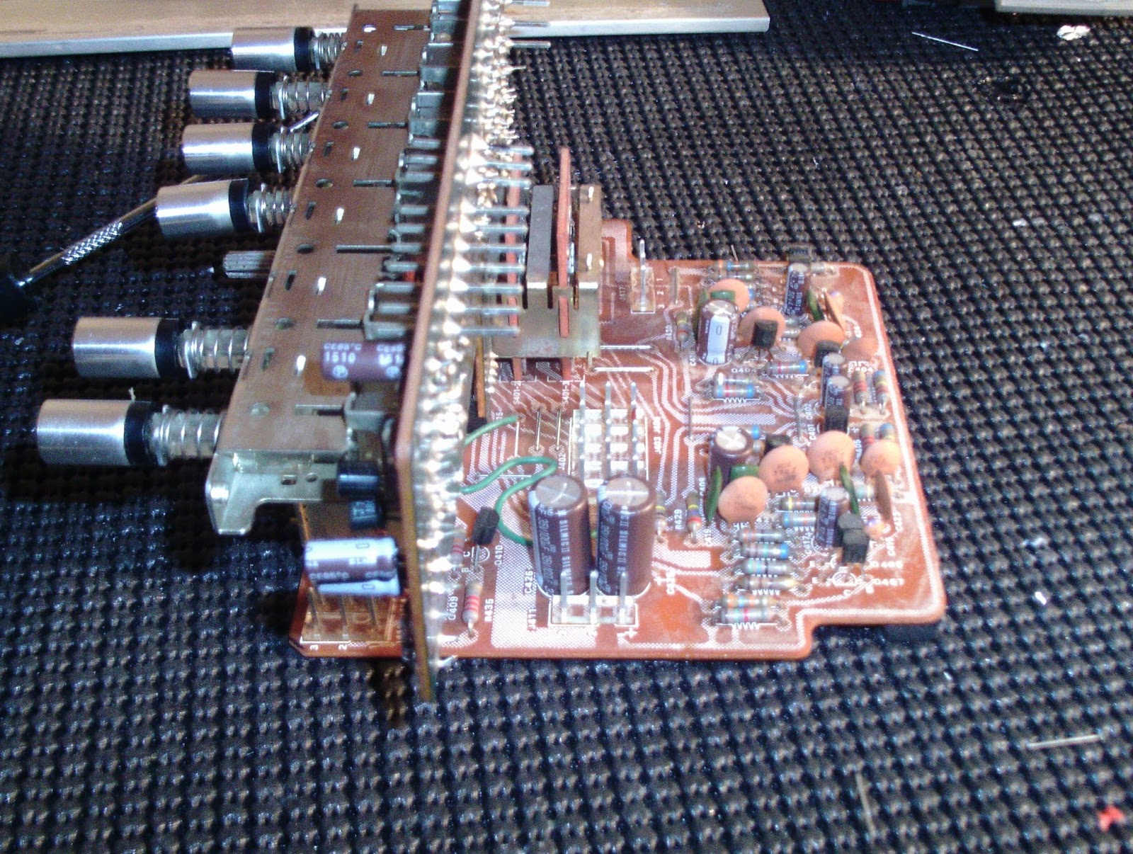
Here is where the 2385 becomes tricky, to truly access the rest of the unit properly to inspect joints and clean switching one needs to fully remove the front chassis plate, same goes for access to the RIAA PCB P400.  


All the low level electrolytic were replaced with polypropylene WIMA film capacitors along with the .22 and .1 MFD mylar films. higher value capacitors were replaced with audio grade Elna Silmic II capacitors. Similar to the 2325/330 pre stages 1/2 tier gain is driven by older Bi-polar Opamps TA7136P IC.


The filter amp assembly connects to the PE00 pre assembly via pin connectors in a 90 degree configuration. it is very important your connectors are solid and you do not bend any leads. low value mylar were replaced with .1MFD WIMA and .22/MFD polypropylene WIMA films. Elna Silmic II were used for larger 47/3.3 MFD values. 


P400 Phono & PS00 Function Switching
P400 was treated as above with high value capacitors replaced with audio grade Elna Silmic II capacitors and low value with WIMA polypropylene film capacitors. Q411 was updated to a 4148 general diode and Q412 to a ultra fast 4005 type.  


Again like the PE00/PT00 stage above the P400 and PS00 assemblies connect in a 90 degree vertical fashion to the front chassis. All the electrolytic were replaced with low impedance, high reliability Nichicon PW type. Germanium diodes were left.

P700 Driver Assembly
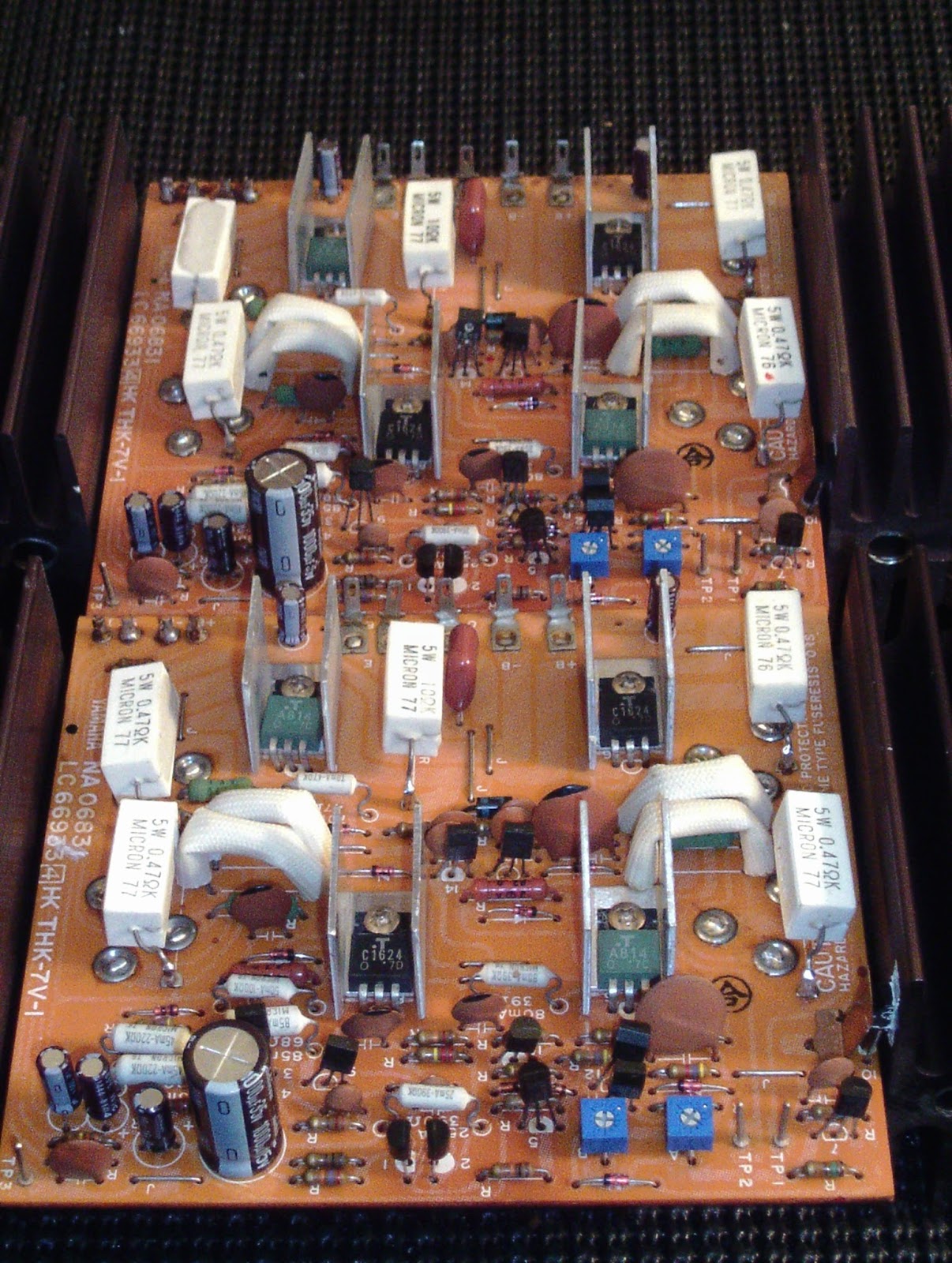
This is a massive assembly with a heatsink sized to the 2500 and capable of massive heat dissipation. With each TO-3 bank sandwiched vertically.  All the rail, filter and input wiring is arranged in a Molex connector for easy removal, pull the SVT mounts and the chassis rails and the entire assembly pulls out of the chassis. This is the time we gut and re-stuff the 6800MFD filter caps, Panasonic THA’s were used here. 

This particular unit came in for a rebuild along with driver issues. Some notorious issues on the P700 are known to eminate from the bias array R731/723 tend to burn up along with diodes Q746 and resistor R721/8703 which consist of 24K and 4.7K values. The trick with Q746 is its a 35V diode which is pretty rare these days, 36 V using a 12/24 or any combination in series will work great rating at 500mW.


New precision 2.2K 500mW Bourns bias and offset potentiometers were replaced along with all VD glass pack diodes to 4148 in series, theirs about 12 on this assembly! Also updated were the first order differential transistors to matched Hfe 1845 type along with tiered Q705/706 to KSC1845 NPN type BJT’s.  Also updated were 3rd order driver BJT’s with new thermal compound at Q723/725 and compliment Q724/726 to To-220 MJE15033/32 type for a more reliable consistent device (2SD610/2SB630 NPN/PNP BJT’s)  All low value capacitors were replaced with 1MFD polypropylene WIMA film capacitors and assorted mylar/film .1/50/250V films. High value capacitors were replaced with high temp (105C) long life capacitors as this stage see significant voltages and heat.


Audio Notizen
Bias beim emitterwiderstanden punkte .68 array fur 25mV
Punkten J719/&29

P200 RF Stages (FM/AM IF)
The RF stages of the 2385 is comprised entirely on the left bank of the chassis, separated from the AF sectionals as it should be. To fully access the P200 PCB you need to remove the left chassis brace and pull the PCB out from the bracket/shielding its nestled in. Removing most of the molex connectors to the P400/PE00 stages will make this easier and give you more room to work as well. All the electrolytics were replaced with my go-to standard for RF which is the low impedance Nichicon PW capacitors, each tantalum capacitor were replaced with PW’s as well. The bi-polar .47 caps were replaced with .47 stacked films. 


PC00 FM Buffer & PB00 Noise AMP
 Like the above stages, all capacitors were replace with low impedance Nichicon PW type and all tantalums replaced with PW’s as well.  Access to PC00 is achieved easier after pulling the P200 assembly out, this is a great time to VERY CAREFULLY clean the tuning capacitor as well. 


Hardware

A new X1Y2 safety capacitor and switching were installed along with a new array of SMD type LED’s for the meters und dial assembly. This is also a good time to replace the meter filter caps with low impedance Nichicon PW’s.

Service Manual Errors Notated
P850 PSC
C853 1000uf 25V ***printing on pCB polarity is opposite what should be

PT00 FIlter Amp
CT23/24 47uf 16V CT24 opposite PCB polarity


PQ00 SOft Start
CQ05 33uf 35V(manual says 22uf 35V)

P700 AMP

C709/710 .47uf 50V NOT PRESENT ON EURO


Audio Notizen
Links
4.8 5.12W (37.09dB)
20.00 88.88W (49.48dB)
24.17 129.81  (51.13)

Recht
5.7 7.22W (38.58dB)
21.94 106.9W (50.28dB)

26.60  157.23W (51.96)


Monday, January 11, 2016

Pioneer SA-8800 Integrated Amplifier

Pioneer SA-8800 Integrated Amplifier 


The Pioneer SA-8800 is an integrated amplifier sold from the late 79 to early 1982. with a fluorometer assembly the SA-8800 touts Pioneers proprietary Non-Switching Amplifier topography further discussed below.  The A/B Class A constant configuration lends to impressive output without the associated distortion of typically b operations. 

Power Supply AWR-182
The power supply is a switching design with relay protected output. All the electrolytics here were replaced with high temp (105C) Panasonic FC capacitors and low impedance high temp (105C) Nichicon PW’s. along with the relay snubber to a 10 OHM/.1 polypropylene. It was noted that one 390 OHM wire wound was damaged and replaced with a 5W WW type. Relay contacts were cleaned and re-installed after a clean-bill. The 10 Ohm 1W resistors had drifted and were updated to 1W MOX type. regulating drivers 2SB682/D712 were updated to modern TO-220 MJE devices. 


Filtering
This unit had oxidization one some of the filter capacitor brackets so new 40MM brackets and all new high grade  12,000 MFD 80V Panasonic THA low ripple filter capacitors installed. The 8800 uses X4 of these 12KMFD capacitors! I was happy with how the aesthetics of this turned out.


EQ/RIAA GWF-113
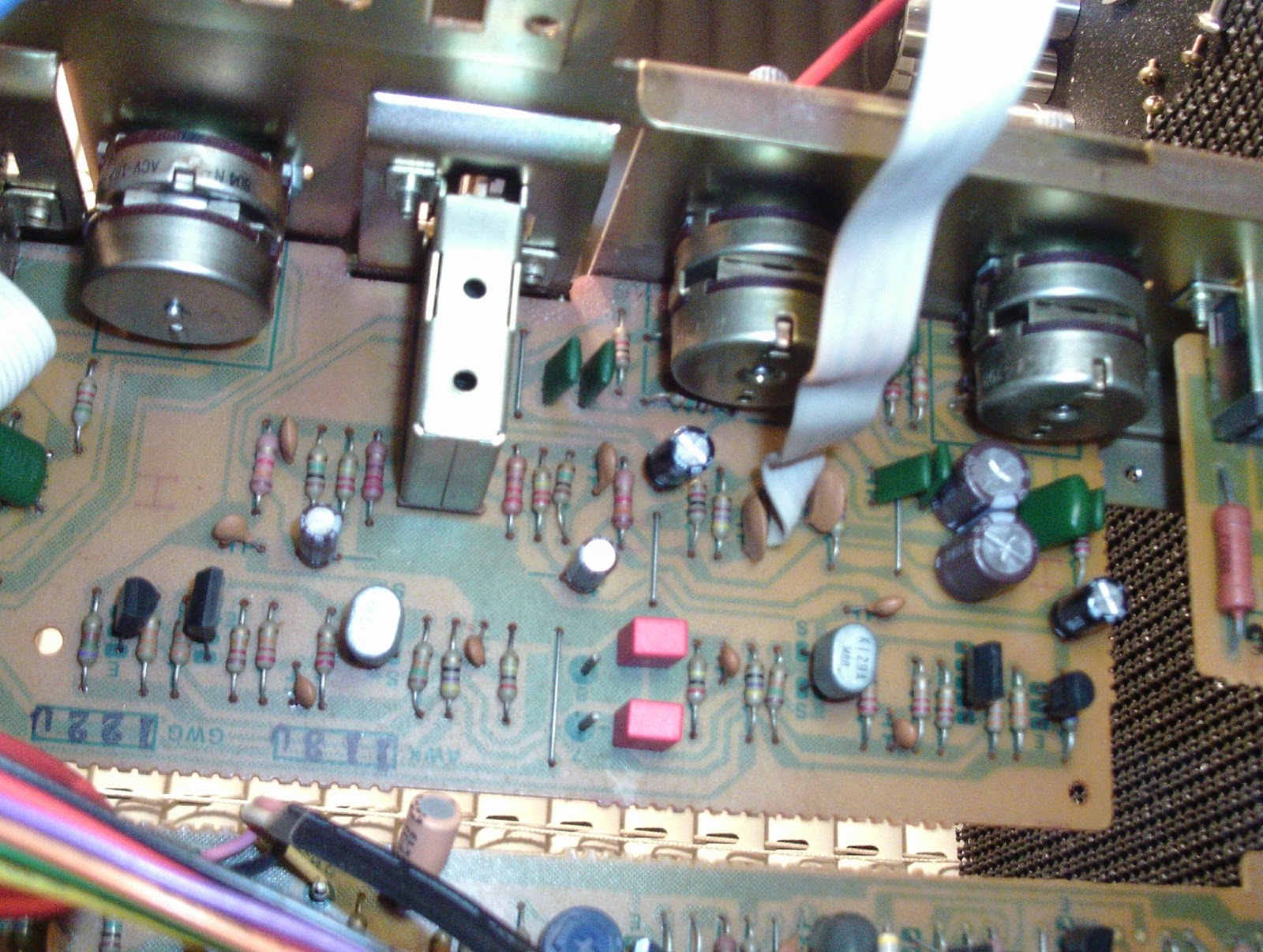
The SA-8800 is known to have a superb RIAA stage, I believe due to the low noise BJT field and super complimentary, symmetric SEPP topography. The RIAA/EQ stage had all the electrolytics replaced with audio Nichicon MUSE and audio grade Nichicon MUSE Bi-polar compliments with low value capacitors to low impedance high reliability Nichicon PW’s. 


Tone  GWG-122 twin FET
The Tone control/pre stage uses like the driver below a complimentary low noise pair of differential Dual FET packages (2SK129A) and a final stage dual BJT (PNP) 2SA798 device.  Like many tone controls we do the electrolytic were replaced with audio grade Elna Silmic and low value microfarad to 1UF high quality polypropylene WIMA film capacitors. Low impedance Nichicon Bi-Polars (4.7MFD) installed as well. With the Meter and RIAA PCB’s removed from the chassis panel you can easily access all the controls and potentiometers at this angle. 


Meter PCB AWV-001
All the electrolytics were replaced with low impedance , high reliability Nichicon PW’s. The potentiometers for meter dialing cleaned pins to amplitude IC HA12010 (Q3/4) were reflowed and Q2 D712 transistor updated to a TO-220 MJE device.


Driver GWH-115
Like the SEPP RIAA stage and two tier pre-amp driver stage the PA uses again a dual differential FET 2SK129A low noise device which are a reliable device still and damn near unobtainable. 1st stage differentials are driven by a dual PNP BJT package with  complimentary differential NPN dual package in a constant current stability mirror arrangement for stabile gain drive. A 2nd their darlington arrangement and final PARA-SEPP circuit for the „Class A-B“ NSA circuit dependent on a SL-RET (IC array) with cleans up our high frequency distortion response as well usually associated with high running class a type configurations.  I am currently reviewing a dual package replacement with slow progress for future repairs. Note also the orientation of the large TO packaged output devices under the PCB and large "skived T-Curve" heatsink. Its lighter than the typical heatsink with a reported 50% increase in dissipation but I still hate these, their flimsy, I personally prefer a large metal and TO-3 device for reliability sakes. I think mounted under the chassis as so leave the legs susceptible to high heat from the radiance above potentially weakening the solder joints on the outputs, I reflowed these in this case. 


All driver electrolytic capacitors were replaced with high temp (105C) low impedance Nichicon PW and high temp Nichicon Bi-Polar capacitors (4.7MFD). All bias mid and offset potentiometers were replaced with precision Bourns trimmers. Final Stage  2sc1913/913 drivers were update to modern complimentary 2073/94o KSC/KSA TO-220 devices.


This SA-8800 had developed a under duress load issue, a final output BJT device was failing under full consumption; thus shunting the rails directly to the output as common with end stage BJT failure resulting in a constant -48V offset. Beyond the voltage indicators this type of failure will not be detected in a standard BJT test under typical 5+/-V DUT's.

cross-referenced new Sanken output devies in a TO-3LP package


Final output results as follows (dual CH)

(120Vac) 10Khz @ 8.00 load
links                          recht

4.73 (2.76W                  5.64   (3.97W 
9.28 (10.76W                10.72 ( 14.36W
15.69 (30.77W              17.96 (40.32W
20.35 (51.76W                  23.70 (70.21W
26.90 (104.40W                  31.46 (123.71W


clipping achieved 
26.90 (104.40W                  31.46 (123.71W


Friday, January 1, 2016

Yamaha CA-1010 & CA-2010 Amplifier Restorations

Yamaha CA-1010 & CA-2010

CA-1010 Yamaha 


CA-2010 Yamaha


Here we have two Yamaha CA Integrated Series amplifiers.  The CA1010 and CA2010 are both similar models with a few distinct differences. 

For starters the CA2010 utilizes all enclosed and some stepped ALPS potentiometers. The other is the control IC for the metered circuits. Another differences is an increase to 22,000 microfarad filter capacitors vs 18KMFD in the 1010 amongst other class A and A/B integrations for stability including all matched FET's. 


Power Supply & Protection PCB’s
For both the CA1010 und 2010 they are almost identical designs for the Power Supply,protections circuit other than the slight difference in lamp rails.  For all the electrolytic’s we replaced with high temp (105C) Nichicon PW and Panasonic FC capacitors. Diodes updated to UF type general diodes. New Omron LY relays were installed as well as at the filter cap PCB.  The power supply on each also use a pair of 10 and 2.2MFD bi-polars which were replaced with Nichicon EP which come in available 105C temperature variances.  I want to note its important to remove the component glue thats used on the 1000MFD/330/220MFD capacitors.
CA1010


CA2010


Pre-Amplifier/ Tone Control
Again very similar topographies used in both the 1010 and 2010 models. As noted one of the biggest differences is the use of enclosed stepped potentiometers for the tone and enclosed pots for the Volume and Balance controls. The few electrolytic’s populated here were replaced with audio grade Nichicon KA capacitors. Both PCB’s incorporate a lot of low Mylar film values, In my experience with the CR series swapping these out with polypropylenes didn’t lend the best results. We did try the .56KMFD with a PP type but resorted back to the Mylar films in this case.

CA1010


CA2010


Function/RIAA, Coupler & Meter PCB Assemblies 
The difference in the tone/RIAA centre is the replacement of IC103/4 with yamaha IC #; MC#00164, in a matched FET, DIP package than the 2010 models. Some models also contain a difference at D101/102 diodes and should replaced the VD1212 glass pack with a 4148 in series respectively.  The CA2010 also introduces the front end 3.3MFD and 1MFD electrolytic’s. The lower value 1MFD were replaced with PP type WIMA film capacitors and all others with low impedance Nichicon PW or audio grade Nichicon KA front and back.  The series of 220/33MFD tantalum capacitors were all replaced and upgraded to audio grade Nichicon KA/PW low impedance electrolytic capacitors in both CA1010 and 2010.
CA1010


CA2010


Meter PCB’s NA06836 and CA1010 both had all the electrolytics replaced with low impedance high temp (105C) Nichicon PW capacitors. The 2010 uses a integrated PM-02 IC where as the 1010 uses a series of BJT circuits for control. The ca2010 lacks the shielding the BJTs need on the 1010 models. 

CA2010


Also dont forget the coupler PCB on the rear chassis, two axial should be replaced with with modern Nichicon TVX, as I noted in other rebuilds the quality of axial's from this time period is questionable.


Drivers
The neat thing about the CA 1010/2010 is the Class A/ B operation feature. Unlike later models that incorporate micro-switching i would advise to never “Hot-Switch” the features, the Class A operation has a significant higher operating parameter as well at about 138-148 Fahrenheit Vs around 100F in A/B. (complied averages: multiple users)

CA1010
All the electrolytics on the 1010 were replaced with high temp (105C) low impedance Nichicon PW’s, the original film was replaced with a high quality polypropylene Panasonic ECW film capacitors. Its important to update again the glass pack VD1212 at D301 with 4148 in series. First stage differentials were replaced with matched 992 BJT’s and 2nd tier TR303/304 with matched 2383YBU BJT’s.  The original 2.2K ClassA/B potentiometers were replaced with 2.2K 1/2W Bourns precision trimmers. Because of the dual operations their are two bias points.

Audio Notizen CA1010
punkten beim TP1 und TP2 fur A/B 25mV 
punkten beim TP1 und TP2 for A 280mV


CA2010
Again, electrolytic here were replaced with high temp, low impedance Nichicon PW’s and films replaced with polypropylene Panasonic ECW’s films. their are no VD glass pack diodes to address on this assembly. The CA2010 differs by using a dual FET differential IC rather than matched BJT compliments.  We did however upgrade the 3rd stage driver compliments to modern On Semi MJE15030/31 TO-220 transistors replacing the 2sc16234/2sa814 compliments.  The 2010 also utilizes a mid-bias point potentiometer which directly correlates to mid stage drive so setting this will greatly affect your bias and output points. All the original 2.2K potentiometers were again replaced with precision Bourns potentiometers.


Audio Notizen CA2010
punkten beim TP1 und TP2 fur A/B 25mV
punkten beim TP1 und TP3 fur 0V
punkten beim TP1 und TP2 fur A 300mV


A different approach I took after comparing fusistors. In the 1010 we have hear all are well with 2% tolerance still, yet on the 2010 most seemed to be drifting about 5% high. Its very important to do your math when converting fusistors to metal films or the like as we did here. The fusistors in this stage short excessive consumption after a failed BJT device, thus shunting and protection the distal operating circuit from the failure point. We want the same characteristics now but in a more reliable resistors such as films. so we take IxR =V V/R .

IE:  
FR301/302 (4.7/230mA) 4.7ohm 1/4W  (4.47 und 4.35) (.2486 W dissipation) 
FR303 (100/50mA)  100ohm 1/4W (100.91)  (.25 W dissipation) 
FR304 (68/85mA)    68ohm   1/2W (68)      (.4913)
FR305 (390/25mA)  390ohm 1/4W (393) (.2873 W dissipation) 
FR306 (47/70mA)  47ohm 1/4W  (47) (.2303 W dissipation) 


Both CA1010 and 2010 filter capacitors were replaced with low ripple Cornell 22,000 microfarad 100V capacitors and fitted. The final step included converting both circuits to Dc rectified LED illumination.  The 14V rails for the lamp assembly needed to be adjusted at the voltage divider so a 180 Ohm 3W resistor was installed with a 1A/100PIV diode in line and 1000MFD filter capacitor for smoothing giving us a correct operating voltage for X5 3.65Fvd White LEDs at 100mA draw. (thanks Joe on the Math)

CA1010


CA2010


3.5V 20ma LED adapted festoons 

LED Conversion notizen fur CA2010

14.8Vac W/ 1A/100PIV diode w/ 1000MFD capacitor @ 19.8Vdc
para: 3.5Fvd 20mA

19.8Vdc - 16.3Vdc working
16.3Vdc / (.020x5) = 163 Ohm V/I=R
16.3Vdc x 0.1 = 1.63W (3W min)


PCB mid-modification procedure; notate inrush R and filter (C)