Monday, February 23, 2015

Marantz 2330 European


Marantz 2330 Euro Restoration

Heres another great 2330 that came in for just a basic restoration. This particular unit is a European variant which basically means it lacks the P600 Dolby integration along with the voltage conversion. 

As far as the 2300 I love to work on these units, the modular molex connections make for a fairly quick tear-down. The 2325 and 2330 are similar in the fact that the regulated supply (P800 is the same in both units, on occasion I have seen different relays though such as a my4 vs a dual throw. 


P800 Power Supply
The design of the relay circuit is interesting to say the least, one caveat is that the thermal breakers attached to the P700 assemblies are actually in series with the coils at J814/815 via the collectors of H806/807.

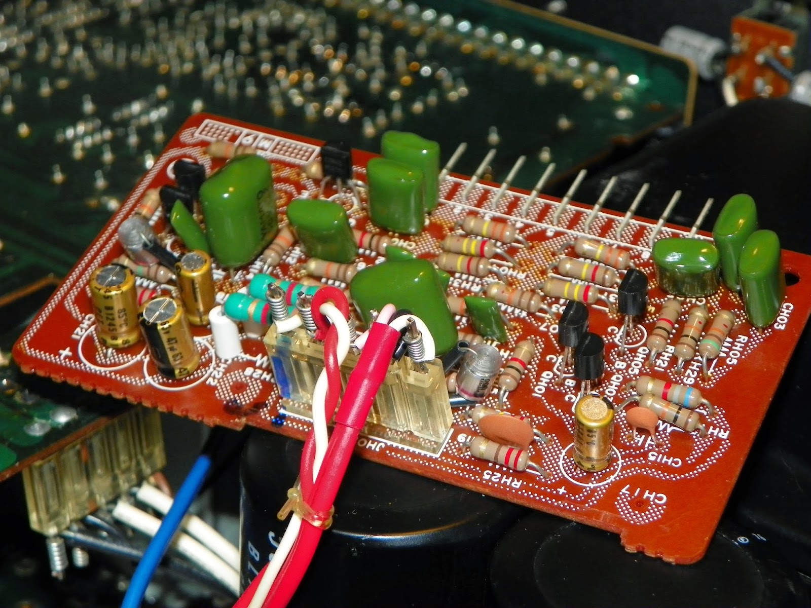
All the caps were replaced with long life, high temp Panasonic FR/FC's, the diodes and zeners I added are a little more robust with a ultra fast 4005 diode. Because of the extent of the glue, most BJT's and resistors along with the film were replaced as well, in the factory they really made a mess of this assembly. The common rectifiers were replaced with TO-220 packaged MUR1620 series and a new Omron MY2 relay added. the sinked transistors had the mica replaced with new compound added as well.


P400 Phono
The lyrics here were replaced with Elna Silmics and an axial packaged TVX Nichicon, as I usually do with smaller capacitance  values, WIMA MKS2 were used.  The smooth red films Im not a fan of were replaced with Panasonic polypropylene ECW films.  As a precursor the potentially problematic 405/406 transistors were replaced with ksc1845s and the rest of the glass diodes replaced with 4148's in series or singled. 


P700 Power Amplifier Assemblies
Per my usual all the lower value capacitance lyrics were replaced with Wima MKS2 and a Panasonic ECW PP films and Elna Silmic II's for the rest. I did use a nice MKP PP to replaced the film at 706 with excellent results I thought. I've tried a few other PP's in this application but I keep returning to MKP's. The differentials were replaced with new thermal compound sandwiched and heat-shrinked together. I really like these more robust heavy duty potentiometers for the dc and Bias personally. I think they beat the modern smaller Bourns unless they tend to drift or don't stabilize during adjustments I keep these type. 


PE01 Tone / Pre-Amp
All the BJT's here tend to be okay, but as a precusor while I was in I like to update them to some more reliable, in this case matched 992'1845's BJT's. All the tantalums were replaced with either Silmics or WIMA MKS2's. CE37/38 are a pair of bi-polar, I used some nice MUSE but any film would be great as well. The small gray films at CE05/06 were replaced with nice Panasonic ECW polypropylenes, I would like to try the MKP's here sometime.  I've tried Mundorfs in the same location in a 2325, but it wasn't anything to write home about. 


PH01 Buffer had the lyrics replaced with all Panasonic FR/FCs. And new 18K 100V Nichicon main filter capacitors were added. These were an exact drop in with the Z-bracket lining up perfect. A new switch with a Vishay X1Y2 and the unit was buttoned up. Should add, probably from removing the euro jack, but a power cord had been spliced with tape. Needless to say a new power cord and tap were added for safety reasons. Like the 2325, P700 as easy access BIAS test points added which makes it straight forward.


Again, the 2300 class has to be my favorite variant to work on and they sound phenomenal, plenty of headroom, great extension and aesthetics to match.


Saturday, February 14, 2015

Kenwood 600 Supreme Integrated Amplifier


Kenwood Model 600/650 Supreme Integrated Amplifier 

I was very excited to get a chance to finally work on one of these, one of Kenwoods TOTL integrated amplifiers, the 600 Supreme. Certainly has an interesting export history. 


The unit came in with an issue of going into protection, , as well as a restoration. The protection circuit and power supply/protection had been properly redone a while back so I skipped that after giving a run through.  I'll say this, the 600 is not for the faint of heart. To do any front panel pcb assemblies I had to completely remove all the switches/pots etc, and remove the chassis section. Same goes for removing the filter caps. Contrary to a few posts i've read, if the unit was put together correctly at the factory you must undo each power transformer to undo the cap mounting bracket. One thing to note is the amazing Alps pot, its a HUGE enclosed stepped attenuator design, extremely solid construction and action, it would costs high dollar to do better IMHO.


Pre-Amp 08-1560-10
This particular board was slightly different than the documented one in the service manual vs the standard X08-1470-01 PCB. All the lyrics were replaced with Silmic II's and lower rated  caps with WIMA MKS2's. This is an interesting pre-amp compared to a lot of Marantz I've seen consisting of 6 FET's for the 4-stage eq phase.  This particular board is a bear because of the tight shielded wiring thats rampant here.


Tone Control X11-1310-00
I used a lot of nice MKS2 films and Silmic II's and MUSE KZ, its a little tighter in here as well. The design is a class A ,FET based Peter Baxandall circuit.  Again it was easiest to remove the chassis mounts and panel hardware on this board than wrestle inside and potential break something. I much prefer to work outside the chassis anyhow.


Filter Assembly - X12-1130-10

When doing the tone control it was easiest to do the Filter Assembly  recap at that time, the boards sandwich each other. Again Silmic II's were used for any lytic. 


Power Amp X07-1440-00
The design is a direct-coupled design, it also incorporates the constant current type dual FET stage i've seen in other Kenwoods such as KA-8100, what is interesting is that it does not utilize an initial input coupling cap. The big issue on these boards are the differential pairs (2sa810) and, again, the constant current regulating (2sc1452). If you do your research you note that these heatsinked to-18 type transistors tend to be failure prone. I had one of the 2sc1452 failing not this unit, causing an intermitted protection issue.   Remember to match the hfe of the  KSA1381's used in the differentials.  Not a whole lot of lyrics on this board either, they were replaced with some nice Silmic II's and a single Panasonic ECW PP film  along with the main course and BIAS pots were replaced with multi turn Bourns. 

Before

After

Mind the different pin-outs of the new transistors (pictured below)


All four filter caps (18Kuf 75VDC) Chems were used, these are an exact drop in dimension wise, the screw terminal makes for fairly quick work after you add rungs. This is the first time I've tried these particular caps and they seem very solid, one of the filter caps I pulled had a nice big soft spot like a over ripened fruit on it.


Thursday, January 22, 2015

Technics SU-8600 Integrated Amplifier


Technics SU-8600 Integrated Amplifier 
Heres an interesting AU-8600 Integrated Amplifier by Technics which was a Panasonic  house brand. Its a fairly large unit with some impressive features such as a nice enclosed multi-stepped attenuator, robust heavy shielding signal wiring and constant current feed dual FET amplifier gain stage based on a limiter and BJT circuit. 


Power Supply
As usual I used some Panasonic FR/FC low impedance high temp capacitors along with Panasonic THA's in the filter, should note a surprise BP is in as well. There are some components to note; TR501/502 the regulator pair and the voltage regulating BJT are a 700BJT case with have poor endurance. These should be replaced with ksa1220/6909 and a ksc 2383. I replaced the general diodes for a more robust 1n4002.  The relay was a standard MY-2 Omron which is a drop in replacement, along without he noted THA filter caps above, no pinout changes to worry about.


Amplifier
I used some nice Elna Silmic II's and FG's throughout the amplifier stage along with some WIMA MKS2 vie been using exclusively now for all low capacitance locations.  I would like to add we zoo those 700# BJT's here again in the pre-driver pairs. I replaced them again with ksa1220/kscd2690A's respectively. Lots of folks have reported noise from these particular locations. I should add removing the heatsink ank to-3 output bank is easy. Putting the assembly back in is another story….This unit features biasing test pin locations which is always a plus.


Pre/Tone
The input/eq and separate tone control assemblies were recapped using Elna/FG's and more MKS2 films along with a ES BP. Note that one the input/eq PCB has a polar lytic between the pre out and ground tap, also the selector shaft needs to be remove to properly contort the board.  I also ended up removing the entire front chassis assembly to angle the main PCB to an accessible point. 


All in a very robust integrated unit, the silver by the way only came with a outer wood case, no metal enclosures except the pre shielding. The black variant sports a case and rack handles from what I am seeing. 

Sunday, January 11, 2015

Marantz 1152DC Integrated Amplifier Repair

Marantz 1152DC Integrated Amplifier


This unit came in going into protection, also noted was a lack of tone controls and filter modes. Some bench upgrades were done while the unit was opened up including recapping the power supply and amplifier. 


Power Supply
The lyrics here were replaced with Panasonic FC/R and Nichicons, their are also two 133B diodes which are anode cathode series diode in a 3 leg package. I've used UF4005s many time soldering in series and bending to a W, their also a nice MUR1620 TO-220 package replacement available.  Also found was a shorted a Zener in the power supply which was replaced. Its interesting to see there is no regulator adjustment in this circuit.  It also interesting to note all four filter caps are actually wired in parallel, plus the AC/DC mode with the added lyrics across the switch.


Relay
The relay was noted to have a shorted 133B diode and replaced as above along with the QN03-05 BJT(Bi-Polar Transistors), the relay which is a 4dpdt Omron was removed and the contact cleaned. The stand off resistors (1/2W) radiate a lot of heat on the PN00 PCB so I expect many units to so at least minimal charring around RN01/RN09/10.

***Its important to add that RN08 has an incorrect voltage across to Base to Emitter voltages. QN05 B should indicate 1.5VDC wheres as QN04 Emitter voltages should indicate 3.4VDC (5%)+/-


Amplifier 
The entire right channels TO-3 output BJT's were shorted along with several 5.6K resistors shorted and Q721 shorted. 

All the lyrics were replaced with Elna Silmic II and Nichicon capacitors, all the 5.6K and 33 ohm resistors were replaced with a more robust Vishay/BC metal film 1W resistors,  Q721 was replaced and new thermal compound was applied to all 8 heatsink mounted BJT's. Along with both banks of MJ21193/94 ONSEMI outputs with new mica insulators and thermal compound. The only adjustment to note is DC offset, the Bias is pre-determined in the circuit.


***Its important to add that the QT01 BJT Base voltage is NOT tied to the +48 rail supply as indicated.


Filter Amp Assembly
All the lyrics were replaced with Nichicons and all BJT's updated, the location of this board fits into a pin slot not he front panel PCB, to clean the pin connection a pick tool and contact clean is accessible with the faceplate removed.


The 1152DC is very moderately rated, with a single channel at a 4ohm load we noted 144W/CH right before clipping began to plateau, its nominal factory rating is 96W/CH @ 4ohm.

All in im not a fan of the pin connections, some I even remove and solder directly to the PCB pads but for a power amp vs an integrated I would highly recommend!

Saturday, December 20, 2014

Marantz 2252B Receiver

Marantz 2252B Receiver


It would seemed that I've been getting a lot of 50 class 22XX receivers lately. The difference between the 2250B/52 and B variants is all substantial in PCB design and layout. 


Power Supply
This is an interesting design. The power supply and power amplifier board and relay are all located on a single PCB section. Typically I do not like this. IIt creates a significant chance of noise and extra heat dissipation issues. 

On the power supply I used Panasonic FC and FRs, a long life high temp capacitor. Two diodes, a common cathode and common anode should be replace here with a more reliable modern MUR1620CTG/CTRG diodes in the same package (TO-220)
 The relay is another 4 contact Omron MY-4-02 type. What makes this one easier than say the 2330 MY4 is at almost an exact drop in replacement pin wise. 


Power Amplifier 
All the caps were replaced with Elna Silmic II's and Nichicon FG capacitors. One thing to mind is C701, the polarity is backwards on the decoupling cap in this stage.
Access is hard here. Your best bet is to remove the filter capacitors mounted under the chassis (same with the 1070 integrated) and remove the speaker switch arms. I think this was a design issue of fabrication VS repair. The large filter caps were replaced with two 6800uf 80V Nichicon KG type, again these are mounted under the amp boards. New mica insulators and thermal compound was applied as well.


Tone/Pre
This is a fairly easy access board by pulling the pots away from the chassis and pulling out. I used Nichicon MUSE BP capacitors at CE23/24 as theirs no significant DC here, ECW PP's would be nice here too. The two small brown films which I don't like (big browns are stay) were replaced with two .22uf ECW PP Panasonic films. The rest were replaced with WIMA MKS2 and Elna Silmic II capacitors.


Phono/Control.
This is another interesting layout. The phono is combined with the tone control and meter switching. The switching function is pulled through a elongated shaft from the faceplate. The meter capacitor and switching is here also.  WIMA MKS2 (small stage) and Elna Silmic II and Nichicon FG capacitors were used here.


Added a new EG1018-ND power switch and safety capacitor,note the extension shaft. And thats a wrap.


One thing to note on the 2252B is a signal meter issue. After talking with several folks it would appear this is consistent as well where the signal meter dances in all functions. I think this is due to the capacitor way back the line VS across the actual meter, at some point I would advise to place a jumper at C422 and pull the cap across the meter, this may cure that.

Overall its a very nice sounding unit once recapped, very robust and very attractive faceplate, getting away from the black and black bevel and going to the silver dial plate.